Lecture
The mode in which the circuit containing parallel branches with inductive and capacitive elements, the current unbranched part of the circuit coincides in phase with the voltage (φ = 0), is called the resonance currents.
Current resonance condition:
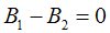
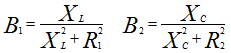
B1 - reactive conductivity of the first branch,
B2 - reactive conductivity of the second branch
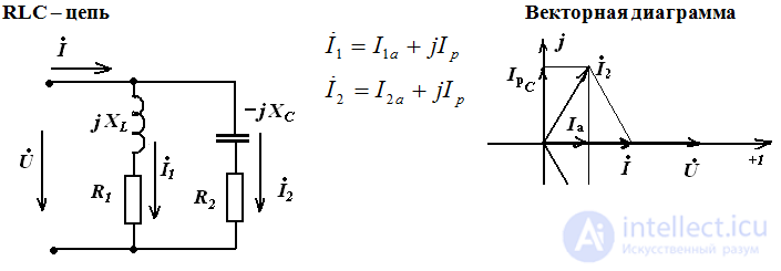
Signs of current resonance:
The reactive components of the branch currents are IPC = IPL and are out of phase in the case when the input voltage is purely active;
The currents of the branches exceed the total current of the circuit, which has a minimum value;
and match in phase
Resonance frequency

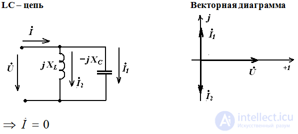
Cases of resonant circuits
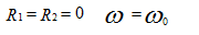
If R2 = 0 resonance occurs when 
Current resonance cases
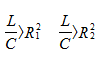
Case 1. One resonance in the circuit, provided:
Case 2. Two resonances in the circuit, at a certain ratio of the resistances of the elements.
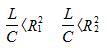
Case 3. No resonance in the circuit - the frequency is an indefinite value, with

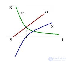
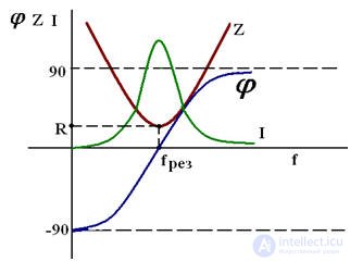
Frequency characteristics of the oscillating circuit

Comments
To leave a comment
Electrical Engineering, Circuit design
Terms: Electrical Engineering, Circuit design