An ideal capacitor when its active resistance is Rc = 0.
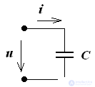
u (t) = Um sin (ωt + ψu)
i = = C = C • ω • Umcos (ωt + ψu)
i = C • ω • Umsin (ωt + ψu + 90 °)
initial current phase ψi = ψu + 90 °
From the vector diagram shows that the current on the capacitor is ahead of the voltage by 90 °
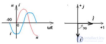

, since φ = -90 °,

and the module impedance
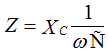
,
therefore, the capacitor resistance is purely reactive and is:
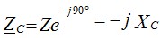
.
Ohm's Law: U = I • (-Xc)
Power on C - element:

phase angle φ = -90 °,
then P = UIcosφ = 0, Q = UIsinφ = -UI, therefore on the C - element energy is exchanged between the source of electrical energy and the electric field of the capacitor, which determines the reactive power Q.
C - the element of work does not make, therefore the active power is equal to 0.


Comments
To leave a comment
Electrical Engineering, Circuit design
Terms: Electrical Engineering, Circuit design