Lecture
Modern electric power industry is based mainly on alternating current. The introduction of alternating current into practice dates back to the 70s of the 19th century.
Compared to other currents, sinusoidal has a number of advantages that allow economically producing, transmitting, distributing and using electrical energy. Currently, the production and transmission of electrical energy are carried out using three-phase current with a frequency of 50 Hz in all countries of the world except the USA and Japan (60 Hz).
Different areas of technology use a wide frequency range of sinusoidal current, depending on technical needs. So in aviation apply a sinusoidal current with a frequency of 400 Hz, as this reduces the overall dimensions and weight of the equipment. In electrothermal installations use the frequency range from 500 Hz to 50 MHz. Frequencies from fractions Hz to 10 GHz are used in radio engineering.
But using sinusoidal current, electromagnetic processes appear that affect the electrical circuits of a more complex nature than in DC circuits. There are a number of features in the work, for example, a capacitor and an inductor. Alternating current generates alternating electric and magnetic fields in these elements. As a result, the phenomenon of self-induction in the inductor and bias currents in the capacitor, which have a significant impact on the processes in complex electrical circuits.
Sinusoidal Electrical Parameters
The sinusoidal function is a periodic function of time, i.e. after an equal period of time, called the period T, the oscillation cycle repeats.
i (t) = i (t + T), where i is the instantaneous current value
The period T corresponds to a phase angle of 2π or 360 °. The duration of the time period T is measured in seconds.
The inverse of the period T is called the frequency and is measured in Hz (the number of periods per second)

The angular frequency ω = 2πƒ (rad / s) is also used, which shows how much the phase angle of the sinusoid has changed over the period, i.e. the rate of change of the phase angle of the sinusoid.
The analytical expression of the instantaneous values of current, EMF and voltage is determined by the trigonometric function:
i (t) = Im sin (ωt + ψi)
u (t) = Um sin (ω t + ψu)
e (t) = Em sin (ωt + ψe),
where Im, Um, Em are the amplitude values of current, voltage and emf;
(ωt + ψ) is the argument of the sine, which determines the phase angle of the sinusoidal function at a given time t; Ψ is the initial phase of the sinusoid, with t = 0
According to GOST ƒ = 50 Hz, therefore, ω = 2πƒ = 314 rad / s.
The time function can be represented as a time diagram that completely describes the harmonic function, i.e. gives an idea of the initial phase, amplitude and period (frequency). Timing diagrams can be observed using a special instrument - an oscilloscope.
Consider an example:
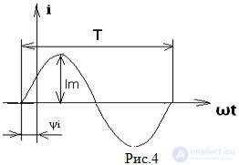
The current function i (t) is shifted to the right from the origin, which means that the initial phase has a negative angle, the current appears earlier on ψi relative to the origin. Current ahead of the origin
But the analytical expression is written as follows:
i (t) = Im sin (ωt + ψi),
The sign “+” or “-” before the initial phase shows how many degrees are not enough for our function to go out of the origin of coordinates. The initial phase is counted from the beginning of the sinusoid, at t = 0, to the origin.
All of the above applies to the functions of voltage u (t) and emf e (t)
When considering several functions of electrical quantities of the same frequency, they are interested in phase relations, called the phase angle.
The phase shift angle φ of two functions is defined as the difference of their initial phases φ = ψu - ψi
If the initial phases are the same, then φ = 0, then the functions coincide in phase;
If φ = ± π, then the functions are opposite in phase.
Of particular interest is the phase angle between voltage and current Fig.5
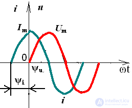
Pic.5
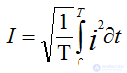
In practice, they use not instantaneous values of electrical quantities, but effective values. The effective value is the rms value of the variable electrical value for the period. It is denoted by the same letter as the amplitude value, but without an index.
For sinusoidal values, the effective values are less than the amplitude values in  times i
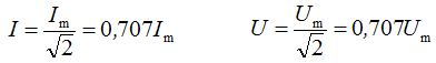
Electrical measuring instruments are graded in current values.
Often for technical calculations it is necessary to know the average value of electrical quantities, but it is taken for half the period, since when determining the average value for a period, the sinusoidal function turns out to be 0.
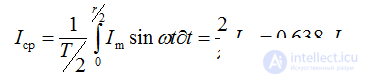
You should pay attention to the fact that the average value is less than the current

Comments
To leave a comment
Electrical Engineering, Circuit design
Terms: Electrical Engineering, Circuit design