Lecture
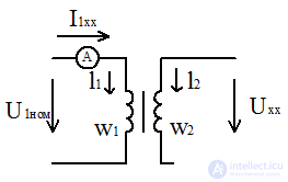
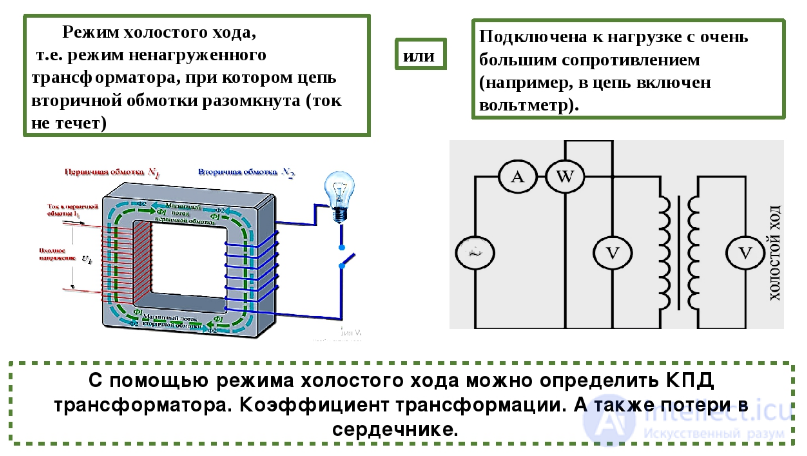 The mode in which the primary winding is turned on at the rated voltage U1NOM, and the secondary winding is open.
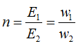
w1, w2 - the number of turns in 1 and 2 windings, respectively.
The mode of operation of the transformer in x.h. the same as in the induction coil.
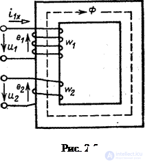
The current in the primary winding I1xx creates (MDS - magnetomotive force  ) , which causes a magnetic flux F (t).
It permeates the primary and secondary windings of the transformer.
F leads in the winding EMF e1 and e2 - real values
E1 = 4.44fw1Fm,
E2 = 4.44fw2Fm.
transformation ratio
In x.x. E1 ~ U1nom, E2 ~ U2x, then
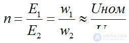
if n> 1 then the step-down transformer
if n <1 then the step-up transformer
The active power consumption of the transformer in x.h.
Ртр хх = Рм + Рэ1 - the general formula
spent on losses in the magnetic circuit and electrical losses in the primary winding of the transformer, i.e.
Рэ1 = 0 because Iхх → 0 => Ртр хх = Рм
Determined by the power factor of the magnetic loss and the impedance of the transformer:

The principle of operation in idle mode. The idling mode is called the mode of operation of the transformer when the secondary winding is open (Fig. 2.5). When powering the primary winding from a sinusoidal voltage source U 1 , the primary current i 1 x (MDS ) causes in the magnetic core a sinusoidal magnetic flux Φ , which, penetrating the windings with the numbers of turns 
 and
and  , induces in them according to the law of electromagnetic induction EMF e 1 and e 2 .

The effective values of these EMFs, i.e., the EMFs in the windings are proportional to the number of turns.
 Transformation ratio The transformation ratio is the ratio of the rated highest voltage of the transformer to the rated lower voltage:
 (2.2) moreover, the nominal voltage refers to the nominal voltage at idle. Since in this mode
  (the voltage drop in the winding is small, since the no-load current I 1 x is much less than the nominal one), a E 2 = U 2 , then for a step-down transformer ( U 1 > U 2 )
 , and for raising (
  )
)  i.e. always
  and
and  (2.3)
(2.3)
Using formulas (2.1), (2.2), (2.3), it is possible to calculate the main parameters of a transformer: transformation ratio, effective electromotive force, coils and magnetic flux.
Emf scattering and voltage dissipation. Some part of the flow, called scattering flow  , does not close along the magnetic conductor, although it covers the primary winding - this part of the flow induces in the primary winding emf dissipation
  which can be represented by a voltage drop
  on inductive dissipation resistance
  where
where  , α
, α  - the flux linkage of the scattering of the primary winding. Really,
  or in complex form
  .
.
The equation of the electric state of the primary winding . We will consider the primary winding of the transformer as a receiver of electrical energy. With this interpretation of the winding function, we choose the positive direction of the EMF against the positive direction of the current i 1X shown in fig. 2.5. Changing the direction of the EMF in the circuit is equivalent to changing the phase of the EMF by 180 ° or changing the sign in the law of electromagnetic induction, which in this case takes the form:  or for self-induced emf
  and emf
  phase ahead of the magnetic flux by 90 °.
The equation written for the primary circuit according to the second Kirchhoff's law (Fig. 2.5):

or
 ,
,
Where  - voltage drop across the active resistance of the primary winding;
  - voltage drop across dissipation resistance
  primary winding. The same equation in complex form:
 . (2.4)
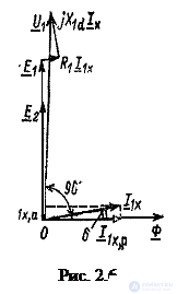 Transformer vector diagram.
The vector diagram of the idling transformer (Fig. 2.6) is constructed on the basis of equation (1.4). With a zero initial phase, the magnetic flux is selected, i.e.  . Current
  phase-wise magnetic flux at a loss angle
  .
.
Relative to vector  ahead of the angle of 90 ° built EMF vectors
  and
and  , since in a complex form, the emf and flux at the chosen direction of the emf are related by
  .
.
Vector  on the basis of equation (2.4) is equal to the sum of vectors
  (the latter is in phase with the vector ) and
  (ahead of current vector at an angle of 90 °).

Comments
To leave a comment
Electrical Engineering, Circuit design
Terms: Electrical Engineering, Circuit design