Lecture
Most often, the term “composite transistor” refers to a Darlington compound transistor.


This scheme in 1953 invented an electrical engineer, an employee of Bell Laboratories Sidney Darlington (Sidney Darlington).
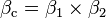
Darlington's composite transistor (sometimes referred to as a Darlington pair, Darlington circuit) is a cascade connection 2 or, rarely, more than two bipolar transistors [1] connected in such a way that the load in the emitter of the previous cascade is the base-emitter junction of the next transistor, that is, transistors connect the collectors, and the emitter of the input transistor is connected to the base of the output.
The current gain of a typical Darlington composite transistor is very high and approximately equal to the product of the current gains of the component transistors, for high-power transistors (for Darlington's circuit that is structurally manufactured in one package, for example, transistor KT825 ≈1000) and for pairs of low-power transistors ≈50000. This means that a small input current of the composite transistor can control the output currents, several orders of magnitude greater than the input control current.
It is also possible to increase the gain of the current by reducing the base thickness in the manufacture of the transistor, but this presents certain technological difficulties and such transistors have very low collector operating voltages not exceeding a few volts. Therefore, relatively high-current and high-voltage circuits use a Darlington pair or a pair of Chiclai.
Sometimes the Darlington circuit is not quite correctly called the "superbet transistor" [2] . Examples of superbet transistors can serve as a series of single transistors KT3102, KT3107. However, such transistors are sometimes combined in a Darlington circuit.
Darlington compound transistors are used in high-current circuits, for example, in voltage regulator circuits, output stages of power amplifiers) and in the input stages of amplifiers, if it is necessary to provide high input impedance and low input currents.
The composite transistor has three electrical leads that are equivalent to the base, emitter, and collector terminals of a conventional single transistor. Sometimes the circuit uses a resistive emitter load of the input transistor to accelerate the closing and reduce the effect of the initial current of the input transistor. The described connection is generally considered as one transistor, the current gain of which, when the transistors are in active mode, is approximately equal to the product of the gains of all transistors, for example, two:
We show that the composite transistor actually has a coefficient β, much larger than that of its both components. Setting the increment dI b = dI b1 , we get:
dI e1 = (1 + β 1 ) dI b = dI b2 ;
dI к = dI к1 + dI к2 = β 1 dI b + β 2 ((1 + β 1 ) dI b ).
Dividing dI c by dI b , we find the resulting differential gain:
β Σ = β 1 + β 2 + β 1 β 2
As always  , it could be considered:
β Σ ≈β 1 β 2 .
It should be emphasized that the coefficients  and
and  may differ even in the case of transistors of the same type, since the emitter current I e2 is 1 + β 2 times the emitter current I e1 (this follows from the obvious equality I b2 = I e1 ) [3] .
The Darlington pair is similar to the Sziklai pair of transistors, named after its inventor George K. Sciclay, also sometimes referred to as the Darlington complementary transistor [4] . In contrast to the Darlington circuit, consisting of two transistors of the same conductivity type, the Sciclay circuit contains transistors of different conductivity type (pnp and npn). A pair of Schiclai is electrically equivalent to a high gain npn transistor. The input voltage is the voltage between the base and the emitter of the Q1 transistor, and the saturation voltage is at least the voltage drop across the diode. Between the base and the emitter of the transistor Q2 usually include a resistor with low resistance. This scheme is used in high-power push-pull output stages when using single-conductance output transistors.
rice Cascode amplifier on bipolar npn transistors.
Composite transistor, made by the so-called cascode scheme, characterized by the fact that the transistor VT1 is connected according to the circuit with a common emitter, and the transistor VT2 - according to the circuit with a common base. Such a composite transistor is equivalent to a single transistor connected in a common emitter circuit, but it also has much better frequency properties, high output impedance and a larger linear range, i.e. less distorts the transmitted signal. Since the potential of the input transistor remains almost unchanged, this significantly suppresses the undesirable influence of the Miller effect and improves the frequency properties.
High gain values in composite transistors are realized only in a static mode, so composite transistors have found wide application in the input stages of operational amplifiers. In high-frequency circuits, composite transistors no longer have such advantages — the limiting frequency gain of the current and the speed of the composite transistors are less than the same parameters for each of the transistors VT1 and VT2 .
Advantages of Darlington and Shiklai composite pairs:
Disadvantages of a composite transistor:
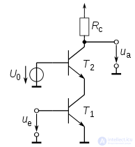
The use of a load resistor R1 can improve some characteristics of a composite transistor. The size of the resistor is chosen so that the collector-emitter current of the transistor VT1 in the closed state (the initial collector current) creates a voltage drop on the resistor that is not enough to open the transistor VT2 . Thus, the leakage current of the transistor VT1 is not amplified by the transistor VT2 , thereby reducing the total collector-emitter current of the composite transistor in the closed state. In addition, the use of the resistor R1 contributes to an increase in the speed of the composite transistor by forcing the closing of the transistor, since the minority carriers accumulated in the base of VT2 when it is locked from the saturation mode not only dissolve, but also flow through this resistor. Typically, the resistance R1 is chosen to be hundreds of ohms in a powerful Darlington transistor and a few kΩ in a low-power Darlington transistor. An example of a Darlington circuit made in a single package with a built-in emitter resistor is a powerful npn Darlington transistor of the KT825 type, its typical current gain is about 1000 at a collector current of 10 A.

Comments
To leave a comment
Electrical Engineering, Circuit design
Terms: Electrical Engineering, Circuit design