Lecture
The transformer is a converter of electromagnetic induction of electric energy of a current of one voltage value into electric energy of another voltage value at f = const.
Transformer - increases the safety of equipment operation.
One of the most common types of electrical equipment. The transformer is designed for a specific frequency.
Nominal operation of the transformer at rated values of currents and voltages, which are indicated on the panel of the transformer and in its passport.
Transformers are:
1. Single phase
Lower and higher. For powering thyristor rectifiers. Miniature. Measuring.
2. Three phase
Raising and lowering.
With the help of step-up transformers, it is brought to a voltage of 10-100 kV and transmitted to the substation. At the stations, the voltage is reduced with the help of step-down transformers. To obtain low voltages 380, 220, 127 V and distribute the receivers.
Application:
Power separating transformers that convert the U network to a working (three-phase).
Single-phase and three-phase for powering thyristor rectifiers of DC motors.
For feeding ferro melting and plasma furnaces. Step-up transformers from 380 V to 50 kV - for powering electron-beam installations and electric precipitators.
Miniature transformers in computing machines.
Measuring transformers U and I, for extending the limits of measuring devices, for safety in high-voltage circuits.
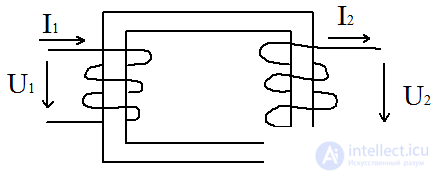
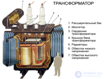
Transformer design.
It consists of 2 windings - the primary winding, to which the power supply is connected and the secondary winding, to which the receivers and the steel magnetic core are connected. If there are many secondary windings, then the transformer is called multi-threaded.
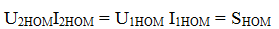
The design of the transformer depends on the dimensions, which are determined by the nominal power.
Snom = Unom
Moreover, we neglect the losses, then:
Transformer equivalent circuit:
In accordance with the principle of operation and the design of the transformer, it follows that its primary and secondary windings are isolated from each other and only an electromagnetic connection exists between them. There is no galvanic coupling between the primary and secondary currents, which complicates the process of analyzing the operation of a transformer. To simplify the analysis of a transformer, an equivalent circuit of a transformer is used. The real transformer has the parameters: Power P1, Q1, S1, cosφ2, U1, I1, R1, X1, E1 - these parameters of the primary circuit are unchanged. Only the parameters of the secondary winding are given:
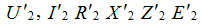
The secondary parameters are given to the number of turns of the primary winding and the voltage U1.
Full equivalent circuit of the transformer
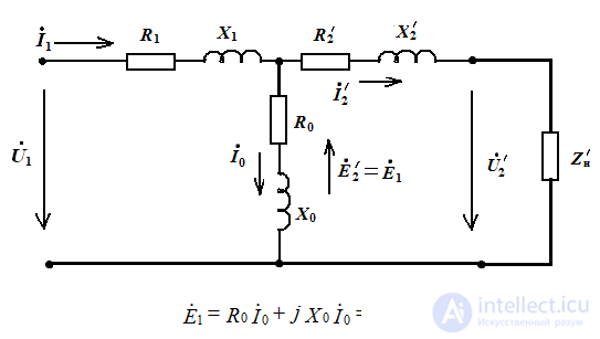
- R0 - active resistance of the primary winding
- R1 - resistance due to magnetic power loss in the magnetic core
- R2ʹ - reduced resistance of the secondary winding
- X1 - inductive resistance of the primary winding, due to the scattering flows
- X0 - inductive resistance due to the main magnetic flux
- X2ʹ - reduced inductive resistance of the secondary winding
n - transformation ratio

Comments
To leave a comment
Electrical Engineering, Circuit design
Terms: Electrical Engineering, Circuit design