Lecture
When designing a circuit for both receivers and transmitters, it is often necessary to attenuate the signal of the pathogen or local oscillator. This is necessary for various reasons. The main thing is the need to ensure the specified parameters of such common electronic equipment as mixers or amplifiers. Attenuators that reduce the signal power (and noise) at the input of a non-linear device perform exactly this task.
The decisive factors include such parameters as the level of nonlinear distortion and the elimination of the effect of an undesirable signal on a nonlinear device, for example, on the local oscillator of the receiving device. Based on the very task of reducing nonlinear distortions, the use of nonlinear elements, such as transistors or diodes, in attenuators (power splitters) is unacceptable.
When solving the problem of attenuation of the input signal, a very important factor is the matching of the wave impedances of the source of the useful signal and the load. For this reason, it is not possible to use a potentiometric voltage divider in the attenuator, which is often used at low frequencies.
U-shaped and T-shaped circuits are used as attenuators (power dividers) with the same input and output impedance. The scheme of the U-shaped attenuator is shown in Figure 1.
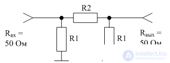
Figure 1 Diagram of the resistive U-shaped attenuator
Resistors in the U-shaped attenuator circuit can be calculated using the following formulas:
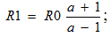
 where R0 is the value of the input and output attenuator resistance;
     a - attenuation of the input signal, expressed in relative units.
The values of the resistances R1 and R2 of the U-shaped attenuator for the most frequently used attenuation coefficients of attenuators are given in Table 1.
Table 1
| A (dB) attenuation | R1 (Ohm) | R2 (ohm) |
|---|---|---|
| 3 | 292 | 17.6 |
| 6 | 150.5 | 37.3 |
| ten | 96.2 | 70.7 |
| 20 | 61 | 247.5 |
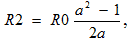
Scheme of the T-shaped attenuator is shown in Figure 2.
Figure 2 Diagram of resistive T-shaped <.nobr> attenuator
The resistors in the T-shaped attenuator (power divider) circuit can be calculated using the following formulas:
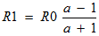 ;
; 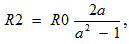
 where R0 is the value of the input and output attenuator resistance;
     a - attenuation of the input signal, expressed in relative units.
The values of the resistances R1 and R2 of the T-shaped attenuator for the most commonly used attenuation factors for attenuators are given in table 2.
table 2
| A (dB) attenuation | R1 (Ohm) | R2 (ohm) |
|---|---|---|
| 3 | 8.5 | 132 |
| 6 | 16.6 | 66.9 |
| ten | 26 | 35 |
| 20 | 41 | ten |
The design of the attenuator varies widely, depending on the frequency range and power dissipation on the resistor of the attenuator.
Quite often, attenuators are used to connect measuring instruments to the transmitter output. In this case, they must be able to withstand considerable power. To this end, the measuring attenuator is supplied with a radiator capable of dissipating heat generated by the resistances of the attenuator. The appearance of such an attenuator is shown in Figure 3.
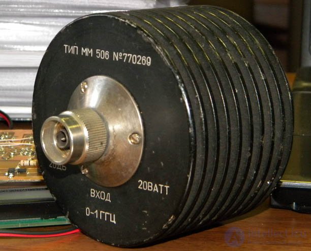
Figure 3. The appearance of a powerful attenuator (power divider)

Comments
To leave a comment
Electrical Engineering, Circuit design
Terms: Electrical Engineering, Circuit design