Lecture
1.2.1. Scheme and functional components of control systems. The automatic control system contains the following functional components (Fig. 1.9):

Fig. 1.9. Functional diagram of ACS
The objects of technical systems are: kinematic mechanisms, electrical, chemical, thermal processes and other technological processes.
The current state of an object is characterized by state variables x i = x i ( t ) (for the exact definition, see p. 3.1.1), which include physical quantities:
etc.
State variables are combined into a state vector
x (t) = { x i } =  .
.
The regulated, or output, variables y j = y j (t) are those variables of the object (controlled process) in relation to which the main control task is formulated. Output variables are combined into an output vector.
y = { y j } =  .
.
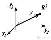
For multi-link kinematic mechanisms, the output vector is usually represented by the Cartesian coordinates of the working point of the mechanism (for example, the gripper of the robot arm, see Example 1.2).
The inputs of the object are the governing bodies to which the actions U j of the actuators of the system are applied.
These are input axes of kinematic mechanisms, input circuits of electrical systems, heating elements and valves of thermal and chemical processes, to which forces or moments are applied. 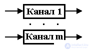 forces of electric drives, electric voltages, etc., causing the movement (development) of a controlled process.
Objects with one input and one output ( m = 1 ) are called single-channel. Accordingly, objects with several inputs and / or outputs are referred to multichannel . The latter may have autonomous
(independent of each other) channels . Often the channels of a multichannel object are interdependent and such an object 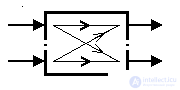 called multiply .
The external environment of the control system includes external processes that influence the behavior of the controlled object. The environment is the source of the following factors (impacts):
 j ( t ) (see clause 1.1.1);
Perturbations include impacts that impede the functioning of an object (resistance forces for kinematic mechanisms, ambient temperature for thermal processes, etc.). Perturbing effects are combined in a vector of perturbations.
f = { f j } =  .
.
Measuring devices (sensors) are designed to obtain information about the object and the external environment of j , i.e. for electrical measurement of state variables, output variables, external setting influences, etc. There are the following types of measuring devices:
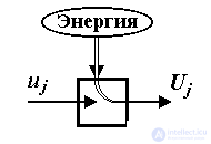
Executive devices are devices designed to amplify low-power control signals u j and create energy effects U j at the inputs of the object, i.e. controlled sources of mechanical, electrical or thermal energy. The most common type of electromechanical actuator is an electric drive or a controlled converter of electrical energy into mechanical energy (see Example 1.2).
The control unit is a computing unit processing the current information about the state of the object and the environment obtained with the help of meters and forming control actions u j , i.e. low-power information signals coming to the actuators of the object. Controls are combined into a control vector.
u = { u j } =  .
.
The functions of the control device include:
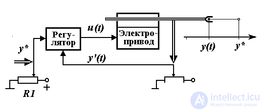
Fig. 1.10. The control system of the robot arm link.
Example 1.2. Control of the position of the kinematic mechanism. The functional diagram of the simplest single-channel control system of a robot arm (RM) is shown in Fig. 1.10, where the following notation is introduced:
y (t) is the current position of the PM link,
y * is the specified position
y '(t) is the measured position
u (t) is the control signal.
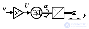
Fig. 1.11. Electric drive
The desired position of the link is entered into the system with the help of the setting potentiometer R1 , which is the simplest setting unit (BZ). Measuring potentiometer R2 performs the functions of a position sensor (measuring device). The actuator is an electric drive consisting of a power amplifier U, an electric motor ED, and a mechanical transmission (gearbox, ball screw drive, etc.) associated with a controlled PM link. The electric drive circuit is shown in fig. 1.11, where U is the voltage at the input of the motor,  - the angle of rotation of the shaft ED.
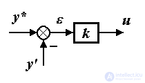
The most important element of the system is the regulator, which is implemented on the basis of analog elements (amplifiers, adders, integrators, etc.) or digital circuits (computers). The regulator calculates the values of the control signal u ( t ) on the basis of information about the given y * and real y ( t ) (or rather, measured y ' ( t )) position of the link. The simplest type of regulator is a proportional, or P-regulator, performing calculations using the formula (algorithm):
(1.6) u ( t ) = k  ( t )
( t )
where k is the proportionality coefficient, - error (deviation, mismatch) calculated as.
(1.7) ( t ) = y ( t ) - y ' ( t ) .
The considered control system is designed to solve the terminal task - the task of moving a PM link to a given final (terminal) position y *: y  y * , or else correcting a position error
  .
.
The block diagram of the position management system, as well as timing diagrams explaining its work, are presented in fig. 1.12, 1.13. The system contains a control unit consisting of a master unit and a controller, as well as an actuator (electric drive) and a measuring device.

Fig. 1.12. Structural diagram of the position management system
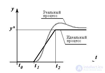
Fig. 1.13.
In the transition process can be divided into three stages. At the beginning of the system operation (from the time point t 0 to the moment t 1 ), it is assumed that the setting knob of the potentiometer R1 and the RM link itself are in the zero position y = 0 . Since the engines of the setting R1 and measuring R2 potentiometers also occupy zero positions: y * = y '= 0 , the error is absent, the control signal u = 0 and, therefore, the drive is at rest. The second stage is the testing of the mastering effect. At time t 1, the master knob is shifted to the position y * , which causes an error signal to appear = y - y ' and the proportional control signal u . The latter, after amplification, drives the electric motor and, consequently, the PM link. At time t 2, measurement potentiometer R2 takes the position y '= y * , the error signal again takes a zero value ( t ) = 0 and the system stops. At the third stage ( t > t 2 ), the system ensures the stabilization of the link in the position y = y * .
It is important to note that the actual behavior of the system will differ from the ideal situation considered. First, due to the inertial properties of the EA and the object (PM link), it is possible to obtain an oscillatory process and overshoot the system when, during the movement, the object first passes beyond the specified position y = y * and then returns. The numerical values of the parameters of oscillation and overshoot characterize the dynamic properties of the system and refer to the so-called dynamic indicators of its quality (see § 1.4.1). Secondly, in real systems, the absolute accuracy of solving the control problem is not ensured - at the end of the transition process (that is, in the steady state) the position of the PM of the real system will differ from the task y * by the amount of the steady y Dynamic and accuracy indicators of the system can be significantly improved using a fairly advanced control algorithm (controller).
To ensure a more smooth movement of the link of the mechanism to a given point, tracking mode is often used, in which the variable setting effect y * ( t ) is used. This mode requires the use of a more complex master unit - software or hardware-implemented generator.
In addition to the simplest displacement sensors, other measuring devices and sensor systems (tachogenerators, optical displacement sensors, range finders and vision systems) can be used to measure mechanical variables.
The task of the control system in question is to move the link in such a way that its current position tracks a given law, or y = y ( t ), i.e. belongs to the class of tracking tasks.
Example 1.3. The control system of the multi-link manipulation robot (Fig. 1.14). Here, various types of master oscillators are used as STs, and measuring devices contain various sensors and computer aids intended for the initial processing of the information received. The output variables of the system are the Cartesian gripper coordinates y 1 , y 2 , y 3 , which change occurs as a result of the turns of the links at angles j . The tasks of the system are moving the robot to a given point, moving along a prescribed path, etc.
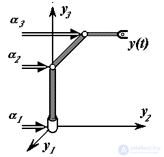
Fig. 1.14. Multilink manipulator
In fig. 1.15 presents a diagram of the control system of the movement of the hand - a natural analogue of the technical system of controlling the position of the RM considered above.
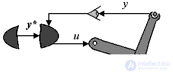
Fig. 1.15. Hand movement control system.
1 .2.3. Integrated control system diagram. Control system can be
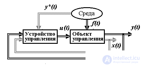
Fig. 1.16
presented in the form of two main blocks interacting with the external environment (Fig. 1.16). The control object (OU) is a complex of system elements most closely associated with the physical nature of the controlled process, i.e. the object itself, measuring and actuating devices. This part of the ACS is usually designed and completed as a whole and is its most rigid part. The dynamic properties of an OS (mathematical model) are found using well-known physical laws.
The control unit (CU) is a unit that performs computational functions that are weakly related to the physical nature of the control unit. The algorithm of its operation depends on the dynamic properties of the controlled process and the tasks solved by the control system. Hardware-modern UU are universal or specialized computer equipment. Their software consists of universal system tools and special application programs that calculate control actions u . These devices are easily adapted to a specific OS and control task, which determines the flexibility and versatility of the SU.

Comments
To leave a comment
Mathematical foundations of the theory of automatic control
Terms: Mathematical foundations of the theory of automatic control