Lecture
The purpose of the work is an analytical and simulation study of the dynamic characteristics of models of linear components of automatic control systems (ACS) and the determination of their parameters using transition and frequency characteristics.
| C. | Link Name | Link Transfer Function |
| Integrating |  | |
| Differentiating |  | |
| Amplification (inertia) |  | |
| Aperiodic 1st order (inertial) | 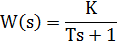 | |
| Aperiodic 2nd order (all roots are real) | 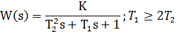 | |
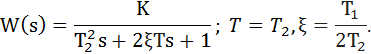
| Oscillatory | 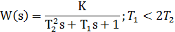 | |
| Conservative | 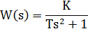 | |
| Integrating with lag (real integrating) | 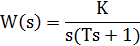 | |
| Differentiation with delay (real differentiating) | 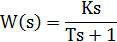 | |
| Forcing | 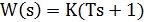 | |
| Isodromic |  |
Often used description of the oscillatory link in the form:
The temporal characteristics of the dynamic link are the dependence of the output signal of the system on time when a certain typical action is applied to its input. Usually, an analysis is performed of the system output on a single jump (Heaviside function) and the impulse function (Dirac function or -function).
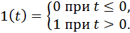
A single jump 1 ( t ) is determined by the conditions:
The reaction of the ACS to a single jump is called the transition function of the system and is denoted by h (t). With a non-unit step effect g (t) = N1 (t), where N = const , in accordance with the principle of superposition, the output reaction of the system will be
y (t) = Nh (t).
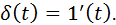
Impulse function  determined by the conditions:

Obviously:
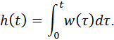
The response of the ACS to the impulse function is called the impulse transient function of the system (the weight function) and is denoted w ( t ). The impulse and transient functions of the system are related by the relation
The MatLab package has two main options for the study of transfer functions and modeling of ACS:
- using the commands of the Control SystemToolbox expansion pack;
- use the Simulink package.
Control System Toolbox [8, 9] is designed to work with LTI-models (Linear Time Invariant Models - linear models with constant parameters) of control systems.
The command that creates an LTI system with one input and one output as a transfer function has the following syntax:

Where  and
and  - the values of the coefficients of polynomials B and A in (3).
For example, if it is required to describe a form of Fermi Fund:
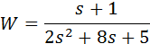
and find out the values of its zeros and poles, then you need to enter the following commands in the MatLab command window:
>> w = tf ([1 1], [2 8 5]) >> zero (w)
>> pole (w)
Investigate the response of the LTI model to typical input effects using commands
>> step (w) >> impulse (w)
You can get on one graph the reaction of several dynamic links at once, if you use commands like this:
>> step (w, w1, w2)
>> impulse (w, w1, w2)
In the examples given, the simulation time is automatically selected. If necessary, you can explicitly specify it in the command.
>> step (w, w1, w2, t),
where t is the simulation time in seconds.
In fig. 1 shows an example of modeling the dynamics of an oscillating element with different parameters:
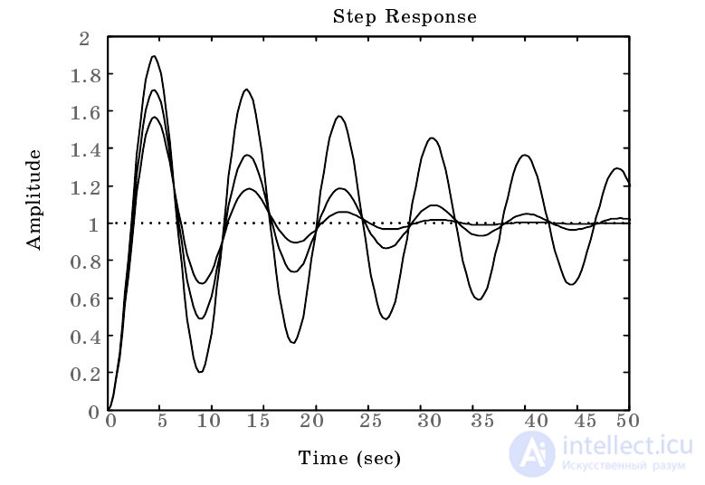
Fig. 1. The study of the reaction of the oscillatory level
>> w = tf ([1], [2 0.3 1]);
>> w1 = tf ([1], [2 0.5 1]);
>> w2 = tf ([1], [2 0.1 1]);
>> step (w, w1, w2,50).
In Simulink MatLab, the PF can be described using the Transferfcn block in the section of the Continuous library. To submit typical impacts, use the Step block from the Sources section. The impulse transient response of a link can be obtained by applying a pulse of small duration and large amplitude (function approximation) to the input at zero initial conditions.
For a visual representation of a complex system as a set of elements and relationships between them, structural schemes are used.
Structural scheme is called the scheme ACS, depicted in the form of connections PF components of its parts.
The structural diagram shows the structure of the automatic system, the presence of external influences and points of their application, the propagation paths of the effects and the output value. A dynamic or static link is represented by a rectangle in which the PF of the link or its mathematical expression is indicated. The effects on the system and the influence of links on each other (signals) are depicted by arrows. In each link, the impact is transmitted only from the input of the link to its output.
Only one input value can act on a dynamic link; therefore, summation and comparison blocks are used. Only signals of the same physical nature can be summed up and compared.
The block diagram can be made according to the equation of the system in the state space or according to the differential equations of the system. In drawing up the structural scheme, it is convenient to begin with the image of the driving force and position the dynamic links that make up the direct chain of the system, from left to right to an adjustable value. Then the main feedback and local feedback will be sent from right to left.
Various methods for the transformation of structural schemes facilitate the determination of the PF of complex ACSs and make it possible to bring the multiloop system to its equivalent single circuit.
Transformation of the structural scheme should be based on the rules. The rules for the transformation of structural schemes can be found in reference books [1, 2], the main ones are given in Table. 2.1.
Table 2.1
| Transformation | Structural scheme | |
| Original | Equivalent | |
| Sequencing |  | 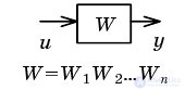 |
| Collapsing parallel connections | 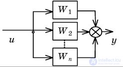 | 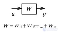 |
| Feedback rollback | 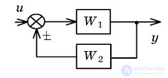 |  |
| Moving node through link forward |  |  |
| Transfer node through the link back |  |  |
| Moving adder through link forward | 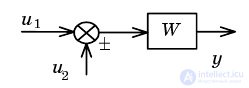 |  |
| Transfer of adder through link back | 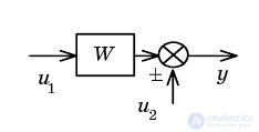 | 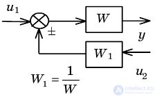 |
| Transfer of direct communication through the link | 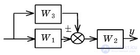 | 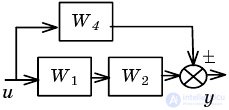 |
| Transferring a node through an adder |  | 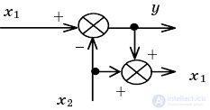 |
| Transfer node through the adder back | 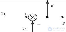 | 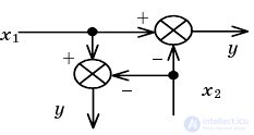 |
Example. Let it be necessary to obtain an equivalent representation for the structure shown in Fig. 2.1.
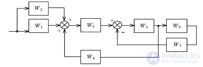
Fig. 2.1. The original structure of the ACS
Conversion includes several stages, shown in Fig.2.2-2.5.
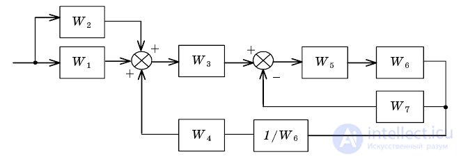
Fig. 2.2. Transferring a node through an adder
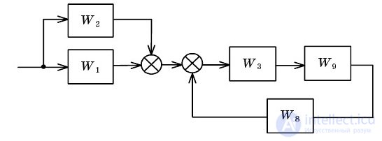
Fig. 2.3. Feedback collapse and serial connection

Fig. 2.4. Feedback collapse and parallel connection
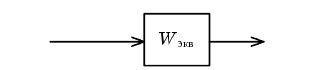
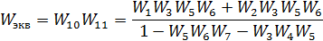
Fig. 2.5. Sequencing
Thus, the first way to transform structural schemes is to directly use the rules given in Table 2.1. The disadvantage of using this approach is that the order of application of the formulas here is quite arbitrary, erroneous steps that complicate the search for a solution are possible.
The second way to get the PF multi-loop system is to use the system model in the form of a signal graph.
The signal graph allows you to graphically describe linear relationships between variables, it consists of nodes (vertices) and directional branches connecting them.
The branch corresponds to the block of the structural scheme, it reflects the relationship between the input and output variables. The sum of all signals entering the node forms the variable corresponding to this node.
The sequence of branches between two nodes is called a path. A contour is a closed path that begins and ends at the same node, and no node is found twice on this path. The contour transfer coefficient is the product of all arcs included in it.
Contours are called non-contact if they do not have common nodes.
The signal graph is uniquely consistent with the structural scheme.
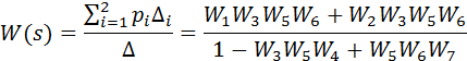
Let X (s) and Y (s) be the input and output variables of the system. Then to calculate the PF of the control system according to its graph, you can use the Mason formula:
Where  - i- th path from the entrance to the exit; N is the number of paths;
  - the determinant of the graph;
  - additional multiplier for the path.
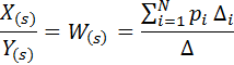
The determinant of the graph is obtained by the formula:
where -  the sum of the transfer coefficients of all individual circuits;
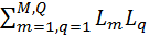 - the sum of the products of all possible combinations of the two not related to the contours;
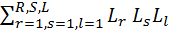 - the sum of the products of all possible combinations of three non-touching contours.
The additional factor for the i- th path is equal to the determinant of the graph, in which the transfer coefficients of the contours relating to this path are equal to zero.
Consider an example of obtaining the multi-loop PF system using Mason's formula for the structure of fig. 1, which corresponds to the graph shown in Fig. 2.6.
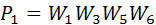
From the entrance to the exit are two ways:
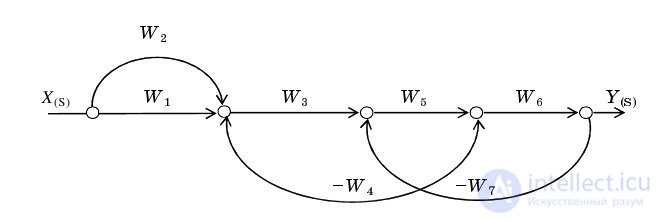
Fig. 2.6. Description of the signal graph control system

There are two contours in the graph:

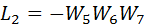
Circuit  concerns the contour
  Therefore, the determinant of the graph is calculated by the formula:
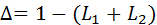
The contours in this example relate to all paths, so additional path multipliers
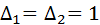
Finally, you can write:
Thus, the use of signaling graphs and the application of the Mason formula allows algorithmizing the process of simplifying the structural scheme.

Comments
To leave a comment
Mathematical foundations of the theory of automatic control
Terms: Mathematical foundations of the theory of automatic control