Lecture
A structural diagram of any complexity can be reduced to an equivalent single-loop (having one main feedback) or to an equivalent open-loop block diagram.
If there are a large number of elements in the system, a structural method is used, according to which the equation of the entire system is obtained on the basis of an algorithmic scheme using several simple rules.
The essence of the method is that by the known transfer functions of the individual elements of the system, which are the detecting links of unidirectional action, using the rules of the series, parallel and counter-parallel (with feedback) links of the links, they receive an equivalent transfer function or transfer function of the equivalent link. The result is a single-circuit closed chain consisting of several equivalent links.
Moreover, this chain can have multiple inputs and multiple outputs. Further, according to the single-circuit scheme, transfer functions between the open inputs and outputs of the system are recorded.
Structural transformations of the circuits are valid if they keep all the input and output signals of the system unchanged.
Schema conversion rules
Structural transformations of the circuits are valid if they keep all the input and output signals of the system unchanged.
The possibility of structural transformations of systems is provided by the principle of superposition and reversibility of signals:
 (2.1) (2.1)
Rule 1: Permutation of the same type of elements (Table 2.1)
Table 2.1
Rearrange the node (adder or links)
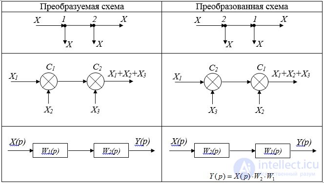
Neighboring elements of the same type can be rearranged in places without changing anything in the scheme itself.
Rule 2: Transfer node from the output to the input of the adder (through the adder against the signal). Such a transfer is accompanied by duplication of the element (adder or link) (Fig. 2.1).
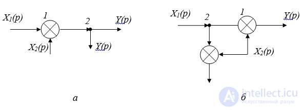
Fig. 2.1. Transfer node:
and - the transformed scheme; b - transformed circuit
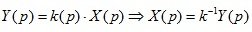
Rule 3: Transferring a node through a link against the signal travel (Fig. 2.2).
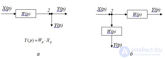
Fig. 2.2. Transfer node through link:
and - the transformed scheme; b - transformed circuit
Rule 4: Transfer node and link through the adder. With such a transfer, it is necessary to install a subtractive device in the node branch (Fig. 2.3).
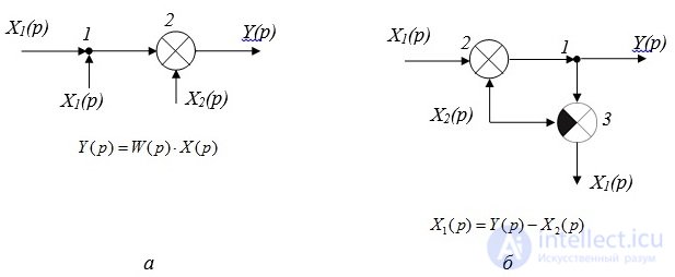
Fig. 2.3. Moving a node through the adder in the direction of the signal:
and - the transformed scheme; b - transformed circuit
Rule 5: Transfer the link through the adder in the direction of the signal (Fig. 2.4).
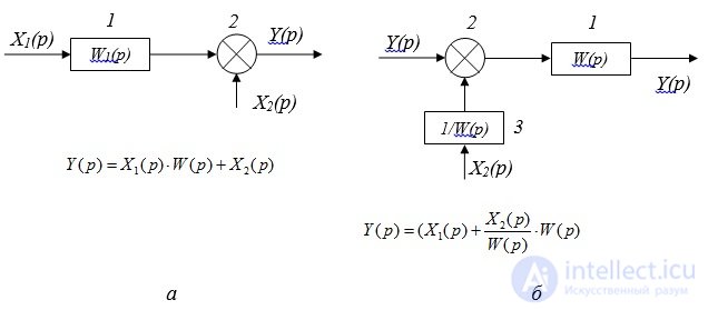
Fig. 2.4. Link transfer through adder:
and - the transformed scheme; b - transformed circuit
In this case, a dynamic link is added to the branch:

Rule 6: Transfer node through the link in the direction of the signal. With this transfer, an additional link with the reverse transfer function must be installed in the node branch (Fig. 2.5)
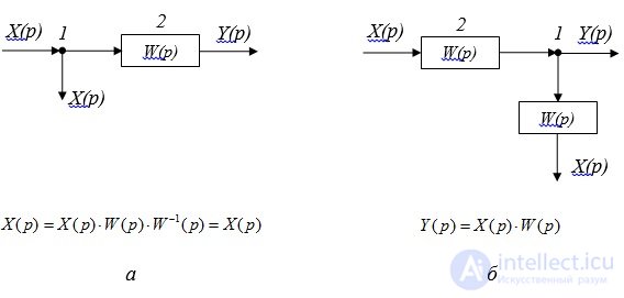
Fig. 2.5. Transfer node through link:
and - the transformed scheme; b - transformed circuit
Rule 7: Transfer the link through the adder against the signal. In this case, the link with the transfer function must be added to the portable branch (Fig. 2.6).
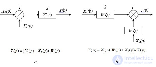
Fig. 2.6. Link transfer through adder:
and - the transformed scheme; b - transformed circuit
Block diagram of a closed two-loop system with negative feedback links (without cross-links)
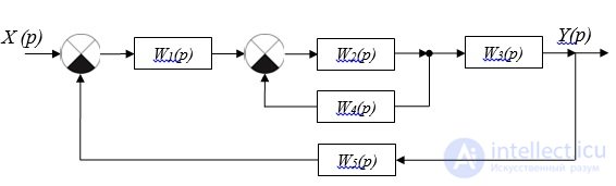
Fig. 2.7. Structural scheme
Formulas for head-to-side connection can be generalized for an arbitrary number of contours nested into one another without cross-feedbacks.
For the structural scheme presented in Fig. 2.7, the transfer function of the system is:
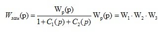 (2.2)
(2.2)
 - transfer function of the internal circuit of the system;
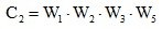 - transfer function of the external circuit.
The transfer function of a closed multi-loop system without cross feedbacks is equal to the ratio of the transfer function of the open loop system to the algebraic sum of the unit and the transfer functions of the elements of nested contours.
Example 1. Simplifying the scheme shown in Fig. 2.8, determine which elementary dynamic link corresponds to the transfer function of the system.
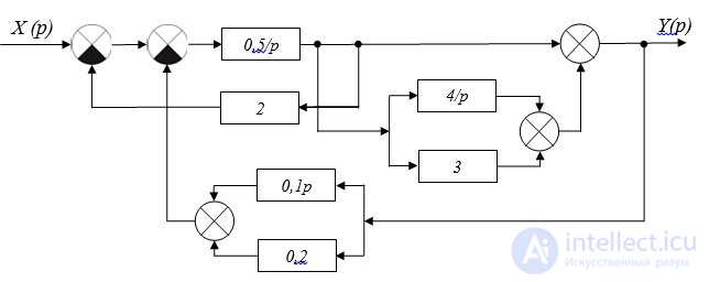
Fig. 2.8. Structural scheme
Decision:
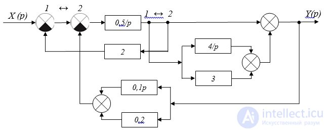
Fig. 2.9. Structural scheme
We receive the block diagram presented on fig. 2.10:
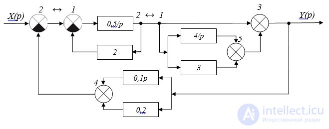
Fig. 2.10. Structural scheme
3. Having added two signals going to adder 4 and two signals going to adder 5 (fig. 2.10), we get the following block diagram (fig. 2.11):
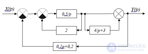
Fig. 2.11. Structural scheme
Parallel connection of links with transfer functions w (p) = 4 / p and w (p) = 3 gives us a link with transfer function w (p) = 4 / p + 3.
The parallel connection of links with transfer functions w (p) = 0.1p and w (p) = 0.2 gives us a link with transfer function w (p) = 0.1p + 0.2.
4. Parallel connection of links in adder 3 will be equal to w (p) = 4 + 4p (Fig.2.12.)
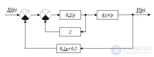
Fig. 2.12. Structural scheme
The transfer function of two links connected in anti-parallel with negative feedback, using the formula (1.19), can be represented as the following expression:  .
.
We write the transfer function of the entire system, presented in Figure 2.12

This transfer function corresponds to the aperiodic link.  with parameters k = 5, T = 3s.

Comments
To leave a comment
Mathematical foundations of the theory of automatic control
Terms: Mathematical foundations of the theory of automatic control