Lecture
The mathematical model of the ACS can be visualized using oriented graphs (digraphs).
Orthographs are used in complex ACS, especially in the management and automation of technological processes in industry, when the description in the form of structural schemes becomes cumbersome and difficult to understand. Consider the simplest digraph of the dynamic link of the ACS.

Fig. one
The SAU graph is a graphical representation of the ACS as a set of vertices corresponding to variables and arcs connecting vertices.
Consider the basic properties of the digraph:
Each arc with an arrow indicating the direction of propagation of the signal, represents a link and is characterized by the operator of the image link (transfer function);
Each vertex marked with a circle is assigned one of the ACS variables (the image of the variable according to Laplace);
The input value of the arc is equal to the variable of the vertex from which this arc starts;
The output value of the arc is obtained as the result of the transformation of the input value by the operator;
If several arcs approach the vertex, then the variable corresponding to the vertex is equal to the sum of the output values of these arcs (analogous to the summing element of structural schemes);
If several arcs emanate from a vertex, then the input values of all these arcs are the same (analogue of the branch point in structural diagrams).
Oriented graph (digraph) can be constructed according to the structural scheme and vice versa. When constructing a digraph according to the structural scheme, it is necessary to follow the following rules:
Modify the block diagram so that in the adders all variables are added with a positive sign, negative signs are entered into the transfer functions of the corresponding links;
Each block diagram adder is replaced by a vertex, which is assigned to the output variable of the adder;
Each dynamic link is replaced by an arc with an operator equal to the transfer function of the link;
Each variable, including input effects, has its own vertex.
Consider an example. In fig. 2 shows a structural initial diagram, in Fig. 3 shows the resulting digraph SAU.

Fig. 2

Fig. 3
Transform the digraph of the ACS can be, like the structural scheme, using the rules of equivalent transformations for digraphs, which can easily be obtained by the same rules for structural schemes.
Consecutive connection of dynamic links.

Parallel connection of dynamic links.

Closed loop with negative feedback.

Closed loop with positive feedback.

Transfer of a branch point through a dynamic link.

Transfer summing link through a dynamic link.

Using Mason's formula for transformation of structural schemes and oriented graphs
When the structural scheme is transformed into a digraph, to find the necessary transfer function, you can use the Mason formula (the rule of non-touching contours), which allows you to get the transfer function linking variables in complex, multi-circuit SAU.
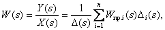
Consider the general form of the formula and explain its components:
| (one) |
Where  - Transmission function
  th separate direct path from
  before
  , calculated as the product of the transfer functions of the arcs included in this path;
 - determinant of the digraph.
| (2) |
Where  - Transmission function
  of the ith closed contour, calculated as the product of the transfer functions of the arcs included in this contour;
 - the product of the transfer functions of the pair (
  th and
  th) closed contours, not related to any arcs or vertices, summation is carried out over all pairs of non-touching contours;
 - product of a triple (
  th
th  th and
  -th) non-touching contours, summation is performed on all triples not related to contours.
 - the determinant of the digraph obtained by removing arcs and vertices
  th separate straight path is determined by the formula (2).
Explain the use of Mason's formula.
At the beginning, all the individual straight paths between the input and output variables are identified, for which the transfer function must be determined. A separate straight path is considered to be such a sequence of arcs and vertices that connects the vertices corresponding to the input and output signals. At the same time, a single straight path should not cross itself at the vertices.
Further, all closed contours are revealed in the ACS digraph. A closed loop is considered such a contour when there is both direct and feedback between two vertices. The transfer function of a closed contour is defined as the product of the transfer functions of all the arcs included in the circuit, taking into account the signs.
After all the closed contours of the digraph have been identified, it is necessary to analyze whether there are contours that do not touch either arcs or vertices, whether there are pairs, triples, etc., of such contours.
On the basis of the obtained is formed the determinant of the digraph by the formula (2).
Determinants of digraphs obtained after removal  -x separate direct paths are also formed by the formula (2), while taking into account only those contours that remain after withdrawal
  th straight path. If, after removing a straight path, there is not a single closed contour left, the determinant of such a digraph is taken equal to one.
As an example, we define the transfer function between  and
and  in the block diagram of ACS shown in fig. 4, believing in accordance with the principle of superposition
  .
.
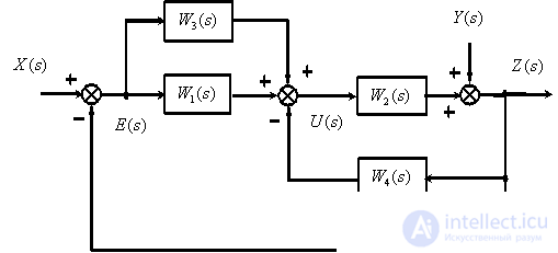
Fig. four
We transform the structural diagram into a directed graph (Fig. 5).
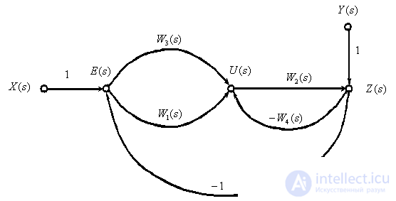
Fig. five
Define straight paths:


Define closed contours:


All contours have a common arc  , therefore there are no non-touching contours. The determinant of the digraph is

When removing the 1st or 2nd straight paths, no closed contour is preserved in the digraph, therefore

The transfer function is

Test questions and tasks
Define a dynamic link digraph.
Explain the procedure for converting the ACS structural diagram to a directed graph.
What is called a separate direct path when using the rule of non-touching contours?
What closed contours are called non-touching?
Determine the transfer function

according to the following structural diagram

Answer:
 .
.
Determine the transfer function

according to the following structural diagram

Answer :
 .
.
Determine the transfer function

according to the following structural diagram

Answer :
 .
.
Determine the transfer function

according to the following structural diagram

Answer :


Comments
To leave a comment
Mathematical foundations of the theory of automatic control
Terms: Mathematical foundations of the theory of automatic control