Lecture
In fig. 4.3.1 shows a diagram of an incoherent optical image recovery system. A small spot of light irregularly moves across the screen of a CRT, forming a raster; the brightness of each point is modulated in proportion to the values of the image samples. Using a projection system containing an incoherent spatial filter with desirable properties, the CRT screen image can then be displayed on a large screen for viewing or on a film for recording. As a rule, the optimal filter that uniformly transmits the image spectrum and having a sharp cut-off outside the spectrum cannot be physically realized.
To restore single-color images, you can use a coherent optical system, the scheme of which is shown in Fig. 4.3.2. In this system, they first take a picture of a CRT screen and make a slide, which is illuminated by a collimated laser beam. The light that passes through the slideshows hits the lens, which in its rear focal plane creates a light field with an intensity distribution proportional to the two-dimensional Fourier spectrum of the spatial distribution of the slit transmittance.
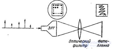
Fig. 4.3.1. Incoherent optical image recovery system.
It is possible to calculate an optical filter that would change the distribution of the amplitude and phase of the light field 6 in the filtering plane in a desired way, that is, it could play the role of a recovery filter. The second lens also performs a Fourier transform and reconstructs the image on the surface of the film.
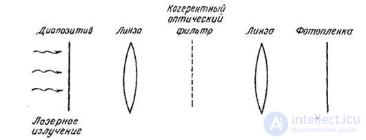
Fig. 4.3.2. Coherent optical image recovery system.
The main advantage of the device, built on the basis of a coherent optical system, is the comparative simplicity of manufacturing a recovery filter. The optimal filter is simply an aperture that only passes a zero order diffraction image.
Electron-optical devices are widely used in image retrieval systems. For example, it is possible to very easily perform interpolation by electrically defocusing the beam on a CRT screen. The disadvantages of this method are that it is difficult to maintain a given shape of the light spot on the entire screen, and the interpolation, as a rule, turns out to be suboptimal. Scanning photographic recorders usually restore a continuous image by projecting a rectangular spot of light onto a photographic film. In most cases, the size of the light spot is chosen equal to the sampling step in order to completely fill the entire image field. This interpolation is simple, but it is not optimal. If in restorative. the device manages to form a very small light spot, then with the help of an additional sub-sweep it is possible with some error to synthesize any desired interpolation function (Fig. 4.3.3). There are three methods for obtaining the values of intermediate image elements for reconstructing with sub-sweep: fitting the spatial function, convolving, and filtering in the frequency domain. In ch. 11 and 15 consider in detail the practical application of these methods.
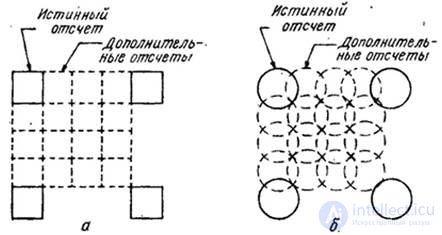
Fig. 4.3.3. Image recovery using the under-sweep method: a - square spot: b - round spot

Comments
To leave a comment
Digital image processing
Terms: Digital image processing