Lecture
Trigger circuits in EWB 4.1 are represented in the Seg'I library by three types of triggers RS, JK, and D, shown in Fig. 9.32. The purpose of the trigger pins is as follows. For all triggers, the outputs Q are direct, Q 'is inverse.
For RS-trigger R - set the trigger to 0, with signal 1 at this input Q = 0, Q '= 1;
S - setting to 1, with signal 1 at this input, Q = 1, Q '= 0; the combination R = 1, S = 1 does not change the state of the outputs and is prohibited. For a JK trigger, J, K are information inputs,> is a clock input; the output above is the asynchronous pre-setting of the trigger in a single state (Q = 1) regardless of the state of the signals at the inputs (functionally similar to the input of the S RS-trigger); the conclusion below is the asynchronous preset of the trigger to the zero state (the so-called cleaning of the trigger, after which Q '= 1); the presence of circles on the output images means that low level signals are active, and for a clock input, that the trigger is switched not on the leading edge of the clock, but on its slice (this is most often called the leading edge of the pulse). For D-flip-flop, input D is informational, the state of this input after applying the clock pulse is remembered by the trigger, i.e. for D = 1 we have Q = 1, for D = 0 Q = 0.


To conduct research on trigger circuits, it is no longer possible to use a logic converter, since a trigger is an element of memory. For this, it is necessary to connect a word generator and LED indicators to the outputs to its inputs. The scheme for investigating the most complex JK trigger is shown in Fig. 9.33. Note that the trigger clock input must be connected to the generator synchronization output.
The ultimate goal of the study is to obtain a truth table, which is one of the main characteristics of a trigger. Getting it is advisable to carry out in the following order:
О to apply active high-level signals (signal 1) to the trigger preset inputs sequentially and record the trigger output state for the case of preset 1 and 0, to check the asynchrony of these inputs, repeat the above operations for different signal states at the clock and information inputs; in the future, only logic zero signals should be fed to these inputs;
О apply signals 0 and 1 in different combinations to the clock and information inputs (at the same time, there must be logical zero signals for all combinations on the inputs of the asynchronous preset) and record the status of the trigger outputs for each combination;
On the basis of the results compile a truth table.
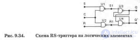
To understand the processes occurring in triggers, we present a diagram of a clocked RS-trigger [20], shown in Fig. 9.34. Actually, the RS-trigger is made on two elements 2I-NOT U3, U4. Setting the trigger to 0 or 1 is possible only if there is an enable clock pulse at clock input C, i.e. such a trigger is completely identical to a JK trigger without preset circuits and additional feedback circuits. To introduce such circuits, it is enough to break the connections at points SI, R1 and introduce into the gap elements 2 OR and elements Ul, U2 replaced by three-input ones. If the input S is connected to the input R through the element NOT, we get a D-trigger, in which the S-input will act as a D-input.
Test questions and tasks
1. What types of triggers do you know what determines their diversity?
2. Determine the code combinations at the output of the word generator for examining the JK-trigger according to the scheme in Fig. 9.33 in accordance with the described methodology. Compare the resulting truth table with the truth table called up by pressing the F1 help key after highlighting the trigger in the diagram.
3. Conduct research in the volume of item 2 for the clocked RS-trigger in Fig. 9.34 and its modifications. The obtained truth tables for the considered modifications are compared with the truth tables of library triggers as described in Section 2.

Comments
To leave a comment
Digital devices. Microprocessors and microcontrollers. computer operating principles
Terms: Digital devices. Microprocessors and microcontrollers. computer operating principles