Lecture
Abstract: Various command coding systems are considered, the relationship between the main computer parameters and the command format, the basic addressing methods and their influence on the operand sampling time, the length of the address field, and the features of their use in programming programs for processing various data structures.
The recording of any team is determined by its format. A command format is a command structure that allows recognition of the purpose of its individual fields.
Based on the definition, the command must contain information about the operation being performed, the addresses of the operands and the address of the memory cell to record the result. This is most appropriate for the command format, which contains the opcode field and three address fields. Such a system for encoding commands is called triaddress (Fig. 11.1, c).
The execution scheme of the three-address command is:
(A 1 ) * (A 2 ) -> A 3 .
Here (A 1 ) and (A 2 ) are the addresses of the memory cells in which the first and second operands are stored, respectively; * - the sign of a generalized operation (for example, addition or multiplication), specified by the field of the operation code (OCP). The sign "->" indicates the transfer of the result of the operation to the memory cell with the address A 3 .

To perform the operation of adding operands located at addresses a and b, with the result written in cell c (c = a + b), one command of the following format is required:
| Cope | A 1 | A 2 | A 3 |
| ADD | a | b | c |
Here ADD is the addition operation code.
The format of the two-address command is presented in Figure 11.1, b. Performing an operation using this command is as follows:
(A 1 ) * (A 2 ) -> A 1 or
(A 1 ) * (A 2 ) -> A 2
Performing the same action c = a + b in a two-address command encoding system will require two commands, for example:
| Cope | A 1 | A 2 | |
| ADD | a | b | a = a + b |
| Mov | c | a | c = a |
The unicast command has the format shown in Figure 11.1, a. Usually computers with a unicast command system have a special structure, which includes a special register (result register - PP). It serves to store the result of an operation and is used as one of the operands when performing an operation (Fig. 11.2).
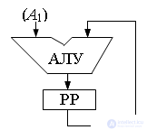
The scheme for performing an operation on a computer with a unicast command system is:
(A) * (PP) -> A or
(A) * (PP) -> PP.
The operation c = a + b in the unicast command system can be performed as follows:
| Cope | A 1 | |
| MOVR | a | PP = a |
| ADD | b | PP = PP + b |
| MOVS | c | c = PP |
The considered command formats are used in the so-called natural order of program execution. This implies that after executing any command that does not explicitly change the order of program execution, the next command is selected from the memory cell located immediately after the cell (or cells) containing the code of the current command. With the four-address coding system of commands (Fig. 11.1, d), the first three addresses perform the same functions as in the three-address command, and the fourth address indicates the address of the cell where the next command being executed is stored. Such a system provides a forced order of execution of program commands. Although it increases the programming flexibility, it has not received practical application. The main reason for this is a significant increase in the size of each command and, accordingly, an increase in the amount of memory required for program placement, while there is no real need for such a coding for each command.
A somewhat special position is the addressless coding of commands. It is used in computers with a stack organization of memory. The access to the cells of such memory is made sequentially using a special stack pointer (CSS), which determines the current working cell. Each cell is equipped with a tag - a special feature of the stored information. Such a computer has the structure shown in fig. 11.3. In addition to the ALU, it consists of two special buffer registers PP1 and PP2. Here, the value of the tags is as follows: Op - the operand is stored in this cell, C is a sign of the presence of an operation code in the cell.
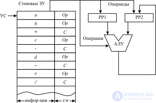
We illustrate the operation of such a computer using the example of calculating the expression ((a + b) * c - d) / e.
In the first two cycles of operation, operands a and b are extracted from memory and placed in the working registers PP1 and PP2. Considering the next cell of the stack memory, the control device determines by its tag that this information is an operation code. This code is sent to the ALU, where the operands stored in the registers are added together with the result written to one of the working registers. Since the operand is stored in the next cell, it is sent to the RR free from the recorded result. After that, the next operation is performed, and so on.
Such a computer structure provides high speed, but requires very complex programming.
An important characteristic of a command is its length, which is the sum of the length of the field of the operation code and the sum of the lengths of the address fields:

where n is the number of address fields in the command.
The maximum number of operations that can be encoded in an operation code field of length n cop is
K max = 2 nCoP
Then, using the known number of commands (K) that make up the command system of a given computer, you can determine the required field length for the operation:
n Kop > = log 2 K.
Naturally, this value should be the minimum possible integer. So, for a computer with a command system of 100 commands, the length of the opcode field will be 7 bits.
If the command address field simply contains the number of the memory cell to which the call is made, then the length of this field is determined as follows:
n A > = log 2 V memory ,
where V is the storage space.
Another formulation of the problem is legitimate - the determination of the maximum storage space (V ZUmax ), which can be accessed with a given length of the address field. In this case
V ZUmax = 2 nadr
Modern computers have, as a rule, storage devices with a minimum addressable unit of 1 byte (1 byte = 8 bits). Therefore, for example, addressing a 1 megabyte memory (1M bytes = 2 20 bytes) requires 20 bits of the address field, and an address field with a length of 16 bits allows access to the memory of the maximum amount of 64 kilobytes (1K bytes = 2 10 bytes).
One of the ways to reduce the length of the address field is to introduce into the computer an additional special small memory block - a register memory (RP). This storage device has high speed and serves to store frequently used information: intermediate results of calculations, cycle counters, components of addresses in some addressing modes, etc. Since the volume of the DF is small, the addressing of its elements requires a relatively short address field. For example, for a register memory with a capacity of 8 registers, only a three-digit address field is required.
It is impossible to solve the problem of reducing the digit capacity of a command only by reducing the number of operands specified in a command and using register memory. The same purpose is served by the use of various methods of addressing operands. In addition, the use of several ways of addressing increases programming flexibility, as in each case allows the most rational way to access information in memory.
Different ways of addressing are based on different mechanisms for determining the physical address of the operand, that is, the address of the actual memory access when executing a command. Determining the set of addressing methods that are put into the command system is one of the most important issues in the development of a computer, significantly affecting its architecture, computing capabilities, equipment size, speed, and other characteristics.
The main addressing methods include the following: direct, direct, indirect, relative.
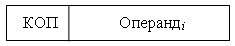
Direct Addressing. The physical address of the operand coincides with the code in the address part of the command (Fig. 11.4). Formal designation:
Operand i = (A i ),
where A i is the code contained in the i-th address field of the command.
Above, when describing methods for encoding commands and calculating the length of the address field, it was assumed that this addressing method would be used.
It is allowed to use direct addressing when accessing both main and register memory.
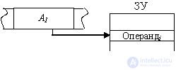
Direct addressing . The command does not contain the address of the operand, but directly the operand itself (Fig. 11.5):
Operand i = A i .
Direct addressing allows you to increase the speed of the operation, since in this case the entire command, including the operand, is read from the memory simultaneously and is stored in the processor in a special command register (RK) for the duration of the command. However, when using direct addressing, the command codes depend on the data, which requires a program change with each change in the immediate operand.
Indirect addressing (Fig. 11.6). The address part of the command indicates the memory address of the memory (Fig. 11.6, a) or the register number (Fig. 11.6, b), which contain the address of the operand:
Operand i = ((A i )).

The use of indirect addressing of an operand from RAM when storing its address in a register memory significantly reduces the length of the address field, while retaining the ability to use the full register capacity to indicate the physical address.
The disadvantage of this method is that additional time is needed to read the address of the operand. However, it greatly increases the flexibility of programming. By changing the contents of a memory cell or register through which the addressing is performed, it is possible, without changing instructions in the program, to process the operands stored at different addresses.
Indirect addressing does not apply to operands in register memory.
Opportunities provided by indirect addressing can be extended if the computer command system provides for certain arithmetic and logical operations on a memory cell or register through which addressing is performed, for example, increasing or decreasing their value by one. So, the addressing, in which after each call to a given address using the indirect addressing mechanism, the value of the address cell automatically increases by the length of the read operand, is called auto-increment. Addressing with the automatic reduction of the value of the address cell is called auto-decrement .
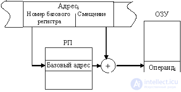
Relative addressing This method is used when the memory is logically divided into blocks called segments. In this case, the address of the memory cell contains two components: the address of the beginning of the segment (base address) and the offset of the address of the operand in the segment. The address of the operand is defined as the sum of the base address and the offset relative to this base:
Operand i = (base i + offset i ).
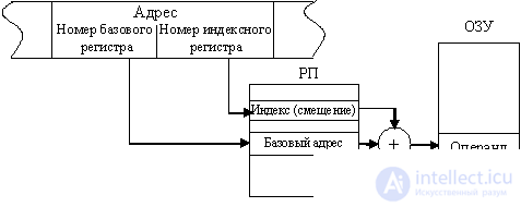
The previously discussed addressing methods can be used to set the base address and offset. As a rule, the base address is in one of the registers of the register memory, and the offset can be specified in the command or register itself.
Consider two examples.
The main disadvantage of relative addressing is the long computation time of the physical address of the operand. But the significant advantage of this addressing method is the ability to create "relocatable" programs - programs that can be placed in different parts of the memory without changing the commands of the program. The same applies to programs that process information according to a single algorithm, located in different areas of memory. In these cases, it is enough to change the contents of the base address of the beginning of the program’s commands or the data array, and not to modify the commands themselves. For this reason, relative addressing facilitates the allocation of memory in the preparation of complex programs and is widely used in the automatic allocation of memory in multi-program computing systems.
You can compare addressing methods according to a large number of various criteria. Table 11.1 presents the characteristics of the considered methods in terms of the time required for sampling the operand, the length of the address field required for one or another addressing method, and the usability of this addressing method when programming. In the appropriate fields of the table, in addition to instructions on the method of calculating the required value, the place of the considered addressing method according to the chosen criterion is also contained. The calculations took into account only the main components that affect the value of the estimated value. Naturally, the criterion that evaluates the flexibility of a particular addressing method when programming cannot be completely objective and depends on the nature of the program.
| Criterion | Addressing | ||||||
| Straight | Indirect | Relate- telnaya | Base index | Directly salient | |||
| RAM 1) | RP | through RAM 2) | through RP | ||||
| Operand sampling time | t ram 3 | t RP 2 | 2t ram 7 | t RAM + t RP four |  five |  6 | t RC one |
| Address field length | log 2 V OZ Have five | log 2 V p P one | log 2 V OZ Have five | log 2 V RP one | log 2 V RP + log 2 V SEGM 4 4) | log 2 V RP 2 | L operand 3 3) |
| Flexibility in addressing data 5) | five | four | 3 | 2 | one | one | 6 |
Accepted notation :
t RAM - time to read information from RAM; t RP - time reading information from the RP; t RC is the time of reading information from the register of commands;  - the time of summation of the components of the address; V RAM - the amount of RAM; V RP - volume RP; V SEGM - segment volume; L operand - the length of the operand.
Notes :

Comments
To leave a comment
Digital devices. Microprocessors and microcontrollers. computer operating principles
Terms: Digital devices. Microprocessors and microcontrollers. computer operating principles