Lecture
A counter is a device whose output signals reflect the number of pulses received at the counting input. The trigger in fig. 9.33 is an example of a simple counter. Such a counter counts to two. A counter formed by a chain of m triggers can count 2m pulses in binary code. Each of the triggers of such a chain is called a counter discharge. The number m determines the number of bits of a binary number that can be written to the counter. The number Kcch = 2m is called the coefficient (module) of the account.
Information is removed from the direct and (or) inverse outputs of all triggers. In the pauses between the input pulses, the triggers retain their states, i.e. the counter remembers the number of input pulses.
The zero state of all triggers is taken as the zero state of the counter as a whole. The remaining states are numbered according to the number of input pulses received. When the number of input pulses Nin> Kch, an overflow occurs, after which the counter returns to zero and the cycle repeats. The counting coefficient, thus, characterizes the number of input pulses required to complete one cycle and return to its original state. The number of input pulses and the state of the counter are mutually determined only for the first cycle.
After the completion of each cycle, voltage drops occur at the outputs of the last trigger. This determines the second purpose of the counters: the division of the number of input pulses. If the input signals are periodic and follow with the frequency F ,,, then the frequency of the output signals is Fout = Fin / Ksch. In this case, the account coefficient is called the division coefficient and is designated as Kdel.
The counter in the division mode uses the output signal of only the last trigger, the intermediate states of the remaining triggers are not taken into account. Every counter can be used as a frequency divider. Therefore, such a device is often called a divider counter. Such dividers have an integer division coefficient. However, the elemental base of modern microelectronics allows the creation of dividers with fractional division coefficients [5, 8].
The symbol of the counters in the diagrams is the letters ST (from the English counter - counter), after the symbol put down a number that characterizes the counting module (for example, 2 or 10 - ST2, CT10).
The main operational indicators of the counter are capacity and speed. The counter capacity, numerically equal to the counting coefficient, is equal to the number of pulses per cycle.
Counter performance is determined by two parameters: resolution Tr „.„ And counter setup time Tust. By resolution is meant the minimum time between two input signals during which no malfunctions occur. The reciprocal of Fmax = l / Tpaz, cx, is called the maximum counting frequency. The setup time of the Tust code is equal to the time between the moment of arrival of the input signal and the transition of the counter to a new stable state. These parameters depend on the speed of the triggers and how they are connected to each other.
Counters differ in the number and types of triggers, how they are connected, the code, the organization of the account, and other indicators. Digital meters are classified by the following parameters [7, 8]:
О account ratio - binary (binary); binary decimal (decade) or with a different base account; with an arbitrary constant and variable (programmable) counting coefficient;
About the direction of the account - summing, subtracting and reversing;
About the way of organizing internal connections - with sequential, parallel or combined transfer, circular.
Classification signs are independent and can occur in different combinations: for example, summing counters are both sequential and parallel transfer, they can have binary, decimal and other counting coefficients.
By introducing additional logical connections - reverse and direct - binary counters are converted to non-binary. Decimal (decadal) counters working with К „= 10 in binary-decimal code (binary - according to the account code, decimal - according to the number of states) are most widely used.
Decimal counters are organized from four-digit binary counters. Excess six states are eliminated by the introduction of additional links. Two options for constructing schemes are possible: the count goes cyclically from 0000 to 1001 and the initial state is 0110B = 6D; the count occurs up to 1111B = 15D (B, D are the designations of binary and decimal numbers). The first option in practice is used more often.
In the totalizing counter, each input pulse increases by one the number recorded in the counter, while the transfer of information from one bit to another, the older one, takes place when the state 1 changes to 0.
The subtracting counter acts in the opposite way: the binary number stored in the counter decreases by one with each incoming pulse. Subtracting counter overflow occurs after it reaches zero state. The transfer from the least significant to the highest here takes place when the state of the least significant digit changes from 0 to 1.
The reversible counter can work as a summing and subtracting one. These counters have additional inputs for setting the direction of the count. The operating mode is determined by the control signals at these inputs. In the EWB program, such counters are presented by IMS 74163 and 74169 (K155IE18, IE17).
Counters with sequential transfer are a chain of triggers in which the pulses to be counted are fed to the input of the first trigger, and the transfer signal is transmitted sequentially from one bit to another.
The main advantage of sequential transfer counters is the simplicity of the circuit. The increase in capacity is carried out by connecting additional triggers to the output of the last trigger. The main disadvantage of sequentially transferring counters is their relatively low speed, since the triggers fire sequentially, one after the other. Counters of this class are not represented in the EWB library.
The maximum counting frequency is determined by the operating mode. If the reading of the counter state should occur after each input pulse, as is the case, for example, when counting to a given number, then the maximum frequency is Fmax = l / [(ml) Tadp + Tcp], where t is the number of digits; Tedp - delay in switching one trigger; Ter - response time of an external element or readout circuit.
Parallel transfer counters consist of synchronous triggers. Counting pulses are fed simultaneously to all clock inputs, and each of the triggers in the chain serves in relation to the subsequent ones only as a source of information signals. Triggers of the parallel counter are triggered synchronously, and the switching delay of the entire counter is equal to the delay of one trigger. These counters use JK and D triggers. In terms of design, they are more complicated than sequential carry counters. The number of bits in these counters is usually small (4 ... 6), since with an increase in the number of bits the number of internal logical connections is growing rapidly.
Counters with parallel transfer are used in high-speed devices. They have a higher noise immunity, since in the pauses between pulses the counter triggers are blocked. Their disadvantages include the lower load capacity of individual discharges due to the additional load of internal connections. The cascade preceding the counter must have sufficient power to control the inputs of several triggers.
Counters with parallel transfer (they are often called synchronous) in the EWB library are represented by counters 74160, 74162, 74163 and 74169 (analogues - K155IE9, IEN, IE18, IE17, respectively).
In a counter with parallel-serial transfer, triggers are combined into groups so that separate groups form counters with parallel transfer, and the groups are connected in series. In the role of groups there may also be ready-made counters. Counters of this type are usually multi-bit. The total score is equal to the product of the score for all groups. In terms of speed, they occupy an intermediate position.
Counters, dividers, designed as independent products, are part of many series of microcircuits. The nomenclature of counters is distinguished by a wide variety. Many of them have universal properties and allow you to control the coefficient and direction of the count, enter the initial number before the start of the cycle, stop the count by the command, increase the number of digits, etc. With the help of ready-made meters, you can solve most of the practical problems that arise before the hardware developer.
In some cases, there may be a need for meters with atypical characteristics. They are created from separate triggers and logic elements.
The design of the counter comes down to determining the number of triggers and organizing the relationships between them and the logic elements, as well as calculating the resolution of the counter (maximum counting frequency).
At the first design step, the specified counting (division) coefficient is converted to binary code. The number of bits of a binary number indicates how many triggers a counter should have, and the number of units determines the number of inputs of a logic element. The inputs of the element are connected to the direct outputs Q of those triggers that correspond to units of a binary number. It should only be taken into account that the first, input trigger displays the least significant digit of the number. The output of the logic element is connected to the zero-setting inputs (R inputs) of all the triggers from which the taps are made, as well as those immediately following them.
The design results are applicable to triggers of different types of logic, however, real schemes may vary in details. Since the forced entry to zero on the R-input for some types of triggers is carried out by logic zero signals (TTL, DTL), in others - by signals of a logical unit (CMOS), in the first case the AND-NOT logic element must be applied, in the second - I. In addition, in the totalizing counter, the rollover of each subsequent trigger should occur when the signal at the output of the previous trigger changes from 1 to 0, so the order of connecting the triggers to each other is important. If triggers with direct control (along the edge 0—> 1) are used in the counter, their inputs are connected to the inverse outputs of the previous ones. In the case of triggers with inverse control, the inputs are connected to direct outputs. By adding a few additional elements to the original circuit, you can expand its capabilities by making a counter with a self-stop (one-time operation) or providing a short-time pulse in the division mode at the output of the last trigger.
We consider the procedure for developing devices based on counters using an example of a digital clock, the functional diagram of which is shown in Fig. 9.35. The watch contains three pairs of indicators to display hours, minutes, seconds and two single indicator-separator. The indicators are controlled from the cont24 and cont60 subcircuits powered by + 5V source. A function generator is used as the master oscillator, the operating modes of which are shown in Fig. 9.36.
It should be noted that presented in Fig. The 9.35 circuit has an extremely low speed, so it was not possible to realize the stopwatch mode by increasing the frequency of the master oscillator. Block cont60 is a counter with an account coefficient KSCh = 60; its functional diagram is shown in Fig. 9.37. The block contains a subcircuit counter cont6 (Kcch = 6) and a binary decimal counter 74160 (K155IE9). Chip K155IE9 (74160) is a decade-long binary decimal counter [7]. It is triggered by a positive clock differential and has synchronous loading (pre-setting of each trigger on inputs A, B, C, D). Several IE9 counters form a synchronous multi-decade counter. Reset all triggers - asynchronous to the common reset input R (CLR ').
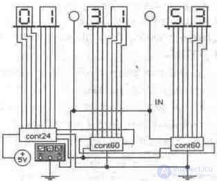
Fig. 9.35. Functional diagram of the clock

Fig. 9.36. Functional generator panel in a clock diagram
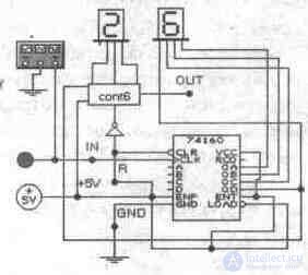
Fig. 9.37. Functional diagram of the counter cont60
The counter contains internal accelerated transfer logic, and all triggers receive a clock differential at the same time. Changes in the output states of triggers coincide in time; therefore, there are no peak noise in the output pulse sequences. The triggering clock edge of the pulse is positive, and for the variant of this microcircuit with Schottky transitions, the buffer element of the clock input has a threshold with a hysteresis of 400 mV, which reduces the sensitivity to impulse noise, and also provides stable switching of triggers with a slowly increasing clock drop.
The IE9 counter is fully programmable, since at each of its outputs you can set the required logic level. Such a preliminary setting takes place synchronously with the difference in the clock pulse and does not depend on what level is present at the count resolution inputs CEP (ENP) and CET (ENT). The low level voltage supplied to the parallel load input PE (LOAD ') stops the count and allows the data prepared at the inputs DO ... D3 (A, B, C, D) to be loaded into the counter at the moment the next positive differential clock pulse arrives (from low to high or when moving from 0 to 1).
Resetting the IE9 counter is asynchronous. If a low voltage is applied to the common reset input R, the outputs of all four triggers are set to low levels regardless of the signals at inputs C (CLK), PE, SET and SER. An internal accelerated transfer circuit is needed to synchronize the multi-decade circuit of IE9 counters. Especially for synchronous cascading, the microcircuit has two resolution inputs: CEP (parallel) and CET (auxiliary, with the code name "trick"), as well as the TC output (RCD - end of counting).
The counter counts clock pulses if both of its inputs CER and CET have a high level voltage. The input SET of the subsequent counter receives the resolution of the account in the form of a high level voltage from the output of the previous counter. The duration of high levels (logical 1 signal) at the output of the vehicle approximately corresponds to the duration of the high level at the output QO of the previous counter.
For IE9 meters, differences from a high level to a low level at the CEP and CET inputs are not allowed if a low level voltage is present at the clock input. Do not apply a positive edge to the PE input if there is a low level voltage at the clock input, and a high voltage at the CEP and CET inputs (during or before the edge). The signals at the SER and CET inputs can be changed if a low voltage is present at the clock input C. When a high level appears at the PE input and the CE inputs are inactive (i.e., at SER and CET it is low), then, together with the subsequent positive clock differential, outputs QO ... Q3 (QA, QB, QC, QD) a code appears from the inputs DO ... D3.
By applying high-level signals to the SET and SER inputs with a low signal level at the clock input, we obtain at the outputs an overlap of the loading codes and the internal account. If, at a low level of the clock signal, positive changes are applied to the SET, SER, and PE inputs, increasing from a low to a high level, the clock difference will change the code at the outputs QO ... Q3 to the next.
With high-level input signals, the K155IE9 (74160) meter consumes a supply current of 94 mA, K555IE9 (74 LS160A) - 32 mA; if all output signals are low, then 101 and 32 mA, respectively. The maximum counting frequency is 25 MHz. The propagation time of the signal from input C to the output of the vehicle ("Account is finished") is 35 and 27 ns, and the reset time (from input R to outputs Q) is 38 and 28 ns for the usual version and the Schottky version.
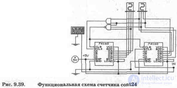
The circuit of the counter cont6 is shown in Fig. 9.38. The counter is executed on three JK-triggers in counting mode (signals 1 are sent to the J- and K-inputs). To ensure the coefficient of counting Ksch = 6, feedback was used on the AND element U2, which is triggered with the code 110B = 6D, and signal 1 from its output through the OR element U1 goes to the R inputs of the triggers, turning them to the zero state. An input R is connected to the second input of element U1 to supply an external reset signal. Since for the counter under consideration and the counter 74160 these signals are different (for the first it is 1, and for the second it is 0), an inverter is switched on at the input R of the counter cont6 (Fig. 9.37). The cont24 hour meter counter layout is shown in fig. 9.39. The counter is made on two IC 74160 and provides a coefficient Ksch = 24.

Test questions and tasks
1. What is a counter, what type are they?
2. How are counters created with an account coefficient not multiple of 2?
3. What is a programmable counter?
4. Design a counter circuit with a counting factor of 3 on JK and D triggers (see diagram in Fig. 9.38).
5. Conduct a simulation of all the functional units of the clock in Fig. 9.35, identify the deficiencies and eliminate them.
6. Conduct a simulation and describe the operation of the counter in fig. 9.39.
продолжение следует...
Часть 1 Digital counters

Comments
To leave a comment
Digital devices. Microprocessors and microcontrollers. computer operating principles
Terms: Digital devices. Microprocessors and microcontrollers. computer operating principles