Lecture
In Sec. 9.2 the IC of the arithmetic logic unit (ALU) 74181 (K155IPZ) was already mentioned in connection with the possibility of using it as a four-digit adder. It was also indicated that this IC provides 32 ALU operation modes depending on the state of the control signals at the inputs M, SO ... S3. Shown in fig. 9.53 scheme based on this IC allows you to quickly implement all the mentioned modes.
Possible modes are set using the switches O, 1, 2, 3 to supply signals 0 (ground) or 1 (+5 V) to the control inputs SO, SI, S2, S3. In the position of the switch M, shown in Fig. 9.53 (signal 0 at input M), 16 arithmetic operations are performed (16 combinations of signals SO ... S3), taking into account the transfer along the input Cn (switch C in the position shown in Fig. 9.53) or without taking into account the transfer (signal 0 at the input Cn) switch C). When moving the key M to another position (at the input M signal 1), 16 logical operations are performed, set by the same switches 0 ... 3.
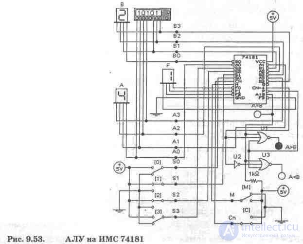
The values of the four-bit operands A and B are set using the word generator and are displayed on alphanumeric indicators in the hexadecimal code. At outputs FO ... F3, the summation result is displayed by the indicator F. With code 1111, at these outputs and with the equality of the operands, the output A = B is transferred to a single state. Since this output is an open collector cascade, +5 V is supplied to it through a 1 kΩ resistor. The output A = B together with the transfer output CN + 4 and the output P transfer confirmations are used to form the signs A> B and A
By changing the state of the signals at the control inputs, you can simulate most of the ALU functions used in microprocessors. Here is a list of these functions.
Logic functions (at input M signal 1); performed bitwise, transfers are not taken into account.
Code 0000 at inputs S3, S2, SI, SO; in this case, the logical function A 'is performed - the data from inputs A are transferred to outputs F with inversion, can be used in the CMA command (hereinafter, the mnemonics of the instructions of microprocessors of the 80xx family of Intel company are used).
0001 - (A + B) '- bitwise OR operation with inversion over operands A and B;
0010 - A'B - operation AND of the inverted operand A and operand B;
UN - 0 - no operation;
0100 - (AB) '- AND operation with inversion;
0101 - B'— inversion of operand B;
IT - AFV - exclusive OR operation, XRA command;
0111 - AB' — operation AND on operands A and inversion B;
1000 - A '+ B - OR operation on inversion A and operand B;
1001 - (A + B) '- OR operation with inversion;
1010 - B - transfer to the output of operand B;
1011 - AB - operation AND, ANA command;
1100-1;
1101 - A + B '- OR operation on the inversion of B and operand A;
1110 - A + B - OR operation, ORA command;
1111 - A - transfer to the output of operand A.
Arithmetic operations (M = 0) without transfer (Cn = 1) and with transfer (Cn = 0, data are given in parentheses):
0000 - A - transfer to the output of the operand (A + 1 - summation of the operand from 1 transfer, increment command).
0001 - A + B - summation operation without taking into account transfer, ADD command ((A + B) +1 - summation with transfer taking into account, ADC command);
0010 - A + B '- operation of summing operand A with inversion of operand B without transfer ((A + B') + 1 - the same, but with transfer);
UN -1 (0);
0100 - A + AB '(A + (AB)' + 1). Further, we will refrain from commenting in the hope that from the foregoing everything is already obvious;
0101 - (A + B) + AB '((A + B) + AB' + 1);
IT - AB-1, SBB command (AB, SUB command);
01H — AB'-1 ((AB) ');
1000 - A + AB (A + B + 1);
1001 - A + B, ADD command (A + B + 1);
1010 - (A + B ') + AB ((A + B') + AB + 1);
lOH-AB-l (AB);
1100 - A + A (A + A + 1);
1101 - (A + B) + A ((A + B) + A + 1);
1110 - (A + B ') + A ((A + B') + A + 1);
1111-A-1 (A).
Control tasks
1. Simulate all the ALU modes listed above (Fig. 9.53), having previously compiled non-repeating combinations at the output of the word generator.
2. Complete the operations without commentary with a description of their functions.
3. Analyze the instruction system of the microprocessor 18080 (KR580IK80) and the possibility of using the logical functions and arithmetic operations of the IC 74181 in them.

Comments
To leave a comment
Digital devices. Microprocessors and microcontrollers. computer operating principles
Terms: Digital devices. Microprocessors and microcontrollers. computer operating principles