Lecture
The purpose of the multiplexers (from English multiplex - multiple) is to switch in a given order the signals coming from several input buses to one output. A multiplexer can have, for example, 16 inputs and 1 output. This means that if 16 digital signal sources are connected to these inputs - generators of sequential digital words, then bytes from any of them can be transmitted to a single output. To select any of the 16 channels, you must have 4 selection inputs (24 = 16), to which the binary address of the channel is supplied. So, to transmit data from channel number 9 at the inputs of the selection, you must set the code 1001. Because of this, multiplexers are often called selectors or selectors-multiplexers.
Multiplexers are used, for example, in MP 18088 for issuing IP addresses and data to the same outputs, which can significantly reduce the total number of outputs of the microcircuit; in microprocessor control systems, multiplexers are installed at remote sites for the possibility of transmitting information on one line from several sensors installed on them.
In fig. 9.17 shows a diagram of a two-channel multiplexer, consisting of elements OR, NOT and two elements I.
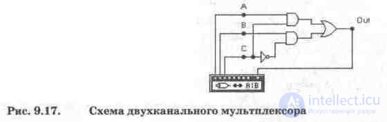
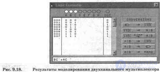
The simulation results of a two-channel multiplexer using a logic converter are shown in Fig. 9.18, from which it can be seen that its output signal is described by the Boolean expression OUT = BC '+ AC, i.e. the signal from channel A goes to the output at address input C = 0, and from channel B to C = 1, which corresponds to the logic of the multiplexer.
Demultiplexers are functionally the opposite of multiplexers. With their help, signals from one information input are distributed in the required sequence over several outputs. The choice of the desired output bus, as in the multiplexer, is ensured by setting the appropriate code on the address inputs. With t address inputs, the demultiplexer can have up to 2 "outputs.
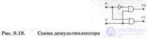
The operation principle of the demultiplexer will be explained using the circuit in Fig. 9.19, on which is indicated: X - information input, A - address input, YO, Y1 - outputs. The circuit contains two AND elements and one NOT element. From fig. 9.19 it is easy to see that at A = 0 the signal of the information input is transmitted to the output YO, and at A = 1 - to the output Y1. It should be noted that demultiplexers as such are not manufactured by the industry, since the demultiplexer mode can be implemented as a special case in other devices - decoders, which will be discussed below.
Test questions and tasks
1. What is a multiplexer, what is its purpose?
2. Using the methodology for analyzing a two-channel multiplexer using a logic converter, examine the internal structure of a dual four-channel multiplexer 74153. From a comparison of the designations of the terminals of this IC and its domestic analogue K155KP2 [7], it follows that their functional purpose is as follows: A, B are address inputs, 1G , 2G are the inverse resolution inputs of the first and second multiplexers, 1С0 ... 1СЗ and 2С0 ... 2СЗ, 1Y and 2Y are the inputs and outputs of the first and second multiplexers, respectively.
3. What is a demultiplexer, for what tasks can it be used?
4. Using the method of analysis of the half-adder with the help of a logic converter, conduct research on the demultiplexer in Fig. 9.19.

Comments
To leave a comment
Digital devices. Microprocessors and microcontrollers. computer operating principles
Terms: Digital devices. Microprocessors and microcontrollers. computer operating principles