Lecture
Abstract: Abstract. We consider a generalized personal computer structure implemented according to the main principle, the structure and main blocks of a 16-bit I8086 microprocessor, the presentation of digital and symbolic information in a computer, the organization of memory and the formation of a physical address in a segmented address space.
Currently, personal computers are produced in millions of copies with a large variety of architectures. However, the most widely used computers built on the basis of microprocessors from Intel or microprocessors with a similar architecture, manufactured by other companies. Therefore, issues related to the organization of modern computers, we will consider the example of this particular architecture.
Intel's microprocessors during their development have so far gone through a series of stages, which with a certain approximation can be characterized by the microprocessor capacity. The world's first microprocessor was the 4-bit Intel 4004 microprocessor released in 1971. The next step was the emergence of a series of 8-bit microprocessors, the most characteristic representative of which was the extremely widespread use of the Intel 8080, the architectural equivalent of which was produced in our country as part of the K580 microprocessor kit. A 16-bit microprocessor, Intel-8086, then developed (the domestic equivalent is the K1810VM80 microprocessor) formed the basis of the first personal computers. Its architecture, designated x86, became the de facto standard for a long period of subsequent development of this area of computing technology. The Intel 286 microprocessor was a transitional stage to the architecture of 32-bit microprocessors IA-32 (Intel Architecture-32), which with certain modifications develops, since the microprocessor released in 1985, the Intel 386. The appearance of the Itanium microprocessor in 2001 marked the beginning of the period of 64-bit microprocessors.
The purpose of this manual is to study the basic concepts of computer architecture. Therefore, we consider it on the example of a computer, which is based on a microprocessor with x86 architecture. In those issues where it is necessary (hardware information protection, organization of virtual memory, etc.), the presentation of the material will be based on computers that have microprocessors with IA-32 architecture.
Personal computer type IBM PC (Fig. 14.1) includes a microprocessor (MP), RAM and input-output devices (UVV), interconnected by a system bus.
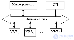
The microprocessor is designed to perform the actual arithmetic and logical operations and control the interaction of computer units. RAM stores the operands and the program during its execution. I / O devices provide for the exchange of information between the computer core (MP and OP) and the means of data input and display. These include monitors, printers, plotters, hard and floppy magnetic disks, and so on.
A computer is built according to the trunk-modular principle, in which all computer units communicate with each other by a system bus intended for exchanging data, address and control information between computer components. As a rule, with such an organization at any time communication can be established only between two computer modules. The system bus determines the overall order of the exchange between any blocks of the computer, as well as the maximum number of used I / O devices. It includes an address bus (ША), a data bus (ШД) and a control bus (ШУ), containing a set of lines on which control signals are transmitted between computer units. The specificity of each particular block is taken into account by specific control devices - controllers that are part of these blocks, for example, the hard disk controller is controlled by the hard disk controller, using information received from the microprocessor via the system bus.
The structure of the 16-bit I8086 microprocessor is shown in fig. 14.2 [8].
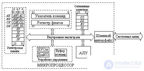
The composition of the microprocessor includes:
ZF - zero flag: equals 1 when a zero result is obtained,
SF - sign flag: set to the highest result bit,
CF - carry flag: captures the fact of transfer from the high-order bit in arithmetic operations,
OF - overflow flag: set to 1 when getting a result outside the valid range of numbers,
PF - parity flag: set to 1 if the lower 8 bits of the result of the operation contain an even number of ones;
control flags are
IF - interrupt enable flag: when the flag is set to 1, the processor recognizes masked interrupts, which allows the microprocessor to respond to special situations that occur in the operation of external devices; if the flag value is zero, then these interrupts are ignored,
DF is a direction flag, used in processing commands of a sequence of bytes in memory: if the flag is 0, the sequence is processed from the element having the smallest address; if the flag is set to 1, the sequence is processed from the highest address to the lowest one,
TF - trace flag: if the flag value is 1, then after the execution of each command in the microprocessor, an internal interrupt is generated, allowing you to switch to the corresponding subroutine (used when debugging programs);
All information in the computer is stored in the form of sets of bits, that is, combinations 0 and 1. Numbers are represented by binary combinations in accordance with the numeric formats adopted for work in this computer, and the character code establishes the correspondence of letters and other symbols to binary combinations.
For numbers there are three number formats:
In a fixed point binary format, numbers can be unsigned (codes) or signed. To represent signed numbers in modern computers, an additional code is mainly used. This leads to the fact that, as shown earlier, negative numbers for a given length of the discharge grid can be represented one more than positive ones. Although computer operations are performed on binary numbers, a more convenient octal, hexadecimal, and decimal representation is often used in the programming languages, in the documentation, and on the display screen.
In binary-coded decimal format, each decimal digit is represented as a 4-bit binary equivalent. There are two main varieties of this format: packaged and unpacked. In a packed BCD format, a string of decimal digits is stored as a sequence of 4-bit groups. For example, the number 3904 is represented as a binary number 0011 1001 0000 0100. In the unpacked BCD format, each decimal digit is in the lower tetrad of the 8-bit group (byte), and the contents of the higher tetrad are determined by the coding system used in this computer, and in this case irrelevant. The same number 3904 in the unpacked format will occupy 4 bytes and look like:
xxxx0011 xxxx1001 xxxx0000 xxxx0100.
Numbers with a floating point are processed on a special coprocessor (FPU - floating point unit), which, starting with the MP I486, is part of the BIS microprocessor. The data in it is stored in 80-bit registers. By controlling the settings of the coprocessor, you can change the range and accuracy of the presentation of data of this type (Table 14.1).
| Data type | Size (bits) | Range | Processing unit |
|---|---|---|---|
| Unsigned integers | |||
| 1 byte 1 word 1 double word | eight sixteen 32 | 0 ... 255 0 ... 65535 0 ... 4294967295 | ALU |
| Signed integers | |||
| 1 byte | eight | -128 ... + 127 | ALU |
| 1 word | sixteen | -32768 ... + 32767 | FPU |
| 1 double word | 32 | -2147483648 ... + 2147483647 | |
| 1 quadruple word | 64 |  (0.92 * 10 19 ) (0.92 * 10 19 ) | |
| Floating point numbers | |||
| real number | 32 (1 + 8 + 23) | (0.34 * 10 39 ) | FPU |
| with double precision | 64 (1 + 11 + 52) | (0.18 * 10 309 ) | |
| with increased accuracy | 80 (1 + 15 + 64) | (0.12 * 10 4933 ) | |
| Binary Decimals | |||
| 1 byte unpacked | eight | 0 ... 9 | ALU |
| 1 byte packed | eight | 0 ... 99 | ALU |
| 10 bytes packed | 80 | 0 ... (99 ... 99) 18 digit | FPU |
OP is the main memory for storing information. It is organized as a one-dimensional array of 1-byte memory cells. Each of the bytes has a unique 20-bit physical address in the range from 00000 to FFFFFh (hereafter, hexadecimal notation is used to write addresses, the sign of which is the h character at the end of the code). Thus, the size of the address space of the OD is 2 20 = 1 MB. Any two adjacent bytes in memory can be considered as a 16-bit word. The low byte of the word has the lower address, and the high byte is the greater. So the hexadecimal number 1F8Ah, which occupies a word, will be located in the memory in the sequence 8Ah, 1Fh. The address of a word is the address of its lower byte. Therefore, a 20 bit memory address can be considered both as a byte address and as a word address.
Commands, bytes and data words can be placed at any address, which saves memory due to its more complete filling. However, to save program execution time, it is advisable to place data words in memory starting from an even address, since the microprocessor transmits such words in one bus cycle. A word with an even address is called word aligned. Unaligned data words with an odd address are valid, but their transfer requires two bus cycles, which reduces the performance of the computer. Note that the required number of read cycles of the data word is initiated by the microprocessor automatically. It should be borne in mind that in operations with a stack, data words must be aligned, and the stack pointer is initiated to an even address, since only data words are involved in such operations.
The command stream is divided into bytes when the instruction queue inside the microprocessor is full. Therefore, command alignment has little effect on performance and is not used.
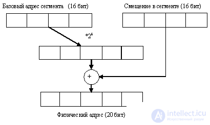
The address space of the OP is divided into segments. The segment consists of adjacent OP cells and is an independent and separately addressable memory unit, which in the basic architecture of a personal computer has a fixed capacity of 2 16 = 64K bytes. Each segment is assigned an initial (base) address, which is the address of the first byte of the segment in the address field of the PD. The value of the physical address cell consists of the address of the segment and the offset of the memory cell relative to the beginning of the segment (intrasegment offset). 16-bit words are used to store segment address and offset values.
To obtain a 20-bit physical address, the microprocessor automatically performs the following operations. The value of the base address of the segment is multiplied by 16 (a shift of 4 bits to the left) and added to the offset value in the segment (Fig. 14.3). The result is a 20-bit physical address value. When summing, a carry may occur from the high bit, which is ignored. This leads to the fact that the OP turns out to be organized in a circular fashion. The cell with the maximum address FFFFFh is followed by the cell with the address 00000h.
Segments are not physically tied to a specific OD address, and each memory cell can belong to several segments simultaneously, since the base address of the segment can be determined by any 16-bit value. Segments can be contiguous, non-overlapping, partially or completely overlapping. However, in accordance with the algorithm for calculating the physical address, the starting addresses of the segments are always multiples of 16

Comments
To leave a comment
Digital devices. Microprocessors and microcontrollers. computer operating principles
Terms: Digital devices. Microprocessors and microcontrollers. computer operating principles