Lecture
The use of microprocessor technology in automatic control systems is primarily associated with the organization of input-output. One of the most common input-output methods is software-controlled, in which the pairing with the control bus system computer is carried out by a set of hardware that provides selection of input-output devices (I / O) and two-way exchange of information from these devices with the control computer. In a popular personal computer (PC) company IBM in the address space of the input-output reserved 32 addresses (from ZOO to 31FH) for the possibility of their use in various experiments on the use of a PC as a control computer. For such purposes, various firms, including IBM [18], manufacture the so-called breadboard with a knife connector type ISA (see below), the design of which allows you to place ICs with a different number of leads on it and then connect them with mounting conductors. Some boards contain buffer elements, address selectors, and bus drivers.
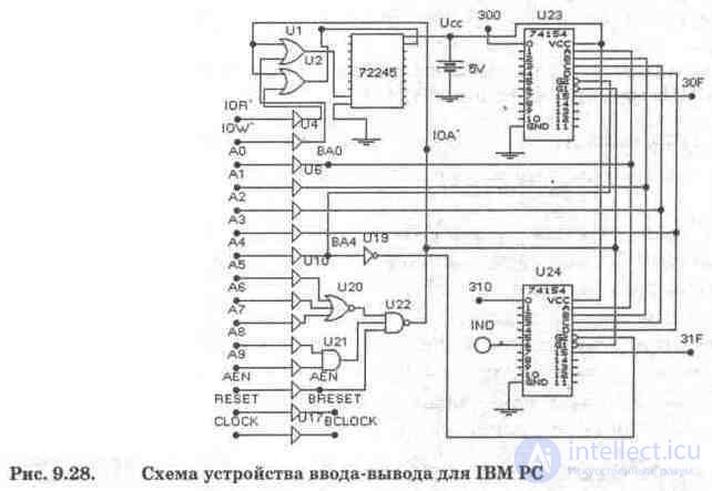
The diagram of the input-output device that allows you to organize two-way communication with a 32-bit air-blast is shown in Fig. 9.28 [18]. The circuit has been slightly changed since the EWB library does not have a bus driver microcircuit 74245 replaced by a subcircuit of two ICs 74244 (indicated by number 72245), as a result of which the control circuit (logic elements U1, U2) is also changed. The second difference is the replacement of two ICs 74244, used in the original as unidirectional buffers, with single buffer elements U3 ... U17, which is caused by the extremely poor arrangement of the terminals of the ICs 74244. This disadvantage is generally characteristic of all digital ICs from the EWB library. Just look at the decoders U23, U24 (domestic counterparts K133IDZ, K1533IDZ, etc.), where the inputs A, B, C, D, Gl, G2 are located on the right side, while it is customary to place them on the left. In other ICs, the inputs and outputs are located alternately on both sides (including 74244). The third difference is the replacement of the 8-bit comparator 74688, which is not in the EWB library, with a combination of logic elements U20, U21, U22.

The diagram of the subcircuit (subunit) 72245 is shown in Fig. 9.29. Subcircuit 72245 can also be performed on buffer elements with three states (see, Fig. 9.16).
The purpose of the IBM PC system bus signals is as follows:
IOW \ IOR '- write and read signals with an active low level for output and input when exchanging with air-blast;
AO ... A9 - address bus signals;
DO ... D7 - data bus signals (in subcircuit 72245). During the write cycle to the air-blast unit, the microprocessor generates these signals before the IOW 'signal, during the read cycle, the input port must provide signals to the data bus before the IOR' signal;
AEN - address selection enable signal, generated by the direct memory access controller (DMA) of the IBM PC motherboard; during the RAP cycle, access to the I / O ports is prohibited, since at this time, the activation of IOW, IOR 'signals is possible;
CLOCK (OSC) - system clock synchronization signal, used as necessary, in the diagram of Fig. 5.8.1 is not involved;
RESET - a signal to set all the functional units of the system to its original state after turning on the power or pressing the Reset button on the system unit; synchronized by the OSC pulse.
After the transmission of these signals through the buffer elements, the prefix B is added to their name, i.e. BIOW ... BDO ... BRESET. Signal IOA '- permission to select the address of the air-blast port - is generated by the address selector on the ICs U20, U21, U22 with the enable state of the AEN signal, for which a low signal level is active.
At the outputs O ... 15 of the decoders U23, U24, address signals of 32 input-output ports (from ZOO to 31FH) with an active low level are generated.
To indicate the status of the outputs in the simplest case, the IND LED can be used (in the diagram it is connected to only one output). The inputs of the decoders Gl, G2 allow, when a low level signal (logical zero) is supplied to them, the formation of a signal at the output of the decoder, determined by the binary code at the address inputs A, B, C, D, is allowed.
Work with air-blast in fig. 9.28 allows you to familiarize yourself with the hardware of software I / O and develop skills in diagnosing and localizing faults in digital control systems. We give an approximate list of such works. 1. Investigation of the IOA 'signal conditioning circuit and the identification (localization) of an existing error. To do this, place the icon of the logic converter on the program’s working field and connect A5 ... A9, AEN signals to its inputs A, B, respectively, and IOA 'signal (U22 chip output) to the OUT output. Then double-click to expand the logic inverter, successively pressing the buttons 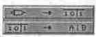 get a truth table and a boolean expression. After that, analyze the truth table, highlighting the binary combination for which IOА '= 0 (column OUT), and in a Boolean expression, the term corresponding to this combination. It should be noted that A = A5, B = A6 ... F = AEN. Find the error in the circuit and correct it (hint - you need to replace the buffer element for one of the signals).
2. The study of the formation chains of air-blast addresses. In the upper right corner of the working field of the program, place the icon of the word generator and connect its output indicator terminals, starting from the lower right digit, with the inputs of AO ... A7. Analyze the address space in the ZOO ... 31FH range and set the required value of the signals at inputs A8, A9 and AEN, then connect grounding elements or a + 5V source from the Passive library to them, simulating logical zero and one sources, respectively. After that, on the generator screen, type a few alternating combinations of binary codes corresponding to address 316H, and in step-by-step mode, by pressing the STEP key, verify the formation of a low active level at the -1 output of the U24 decoder, to which the IND indicator is connected; with a correctly selected binary combination, its glow stops. Similarly, all other outputs of the decoders are checked.
Let us show that in order to determine the state of signals at the address inputs A5 ... A9 in the address range 300H ... 31FH, it is necessary to convert their sixteen-decimal code to binary, replacing each digit with a tetrad with a weight of bits 8-4-2-1, t. e. ZOO = 0011 0000 0000, 31FH = 0011 0001 1111, from which it can be seen that in the indicated range of addresses A9 = A8 = 1 and A7 = A6 = A5 = 0 (address counting starts from the lowest, zero bit). Therefore, to the inputs of A8, A9 you need to connect a signal source of a logical unit (+ 5V), and ground to the inputs of A5, A6, A7.
3. Investigation of the control circuits of the bus driver 72245. To check the correct functioning of this node to the inputs of AO ... A9, connect the signal sources of logical zero and logical unit in the combination corresponding to address 316H, and ground the AEN input if the error in paragraph 1 has not been fixed 1. With proper switching after turning on the power supply, the IND indicator should turn off. To control IOR ', IOW inputs, use a voltage source with a given internal resistance from the Passive library and a switch from the Control library controlled by the R key (read). For a power source, it is necessary to choose its EMF and internal resistance correctly, taking into account the parameters of the 155 series IC.
Let us show that the IOR and IOW signal simulation circuit is shown in Fig. 9.30 a.m. In the position of the switch shown on it, a write signal is generated (reading is prohibited, since IOR 'is a logic unit signal that prohibits such a mode). When you press the R key, a read signal is generated from the air-blast connected to address 316H, while writing is prohibited for the above reasons.
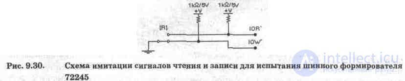
The voltage source EMF for the 155 Series IC is 5 V, and its internal resistance is approximately equal to the output resistance of the 155 series base element.
From fig. 9.29 it is seen that the control inputs G1 'of the bus driver 72245 (write permission in the air-blast) and G2' (read permission from the air-blast) are connected to the outputs of the two-input logic elements OR U1 and U2, respectively, which realize the functions of the two-input elements AND for active inverse signals on inputs, i.e.

To check the recording mode, connect the word generator to the DO ... D7 inputs of the 72245 generator, and the indicators from the Indie library are connected to its two outputs, for example BDO and BD7. By setting the appropriate combinations of an eight-bit code at the input, we will observe the transmission of signals through the bus driver on the air-blast unit connected to address 316N ... To check the reading mode from the air-blast unit, the word generator and indicators are swapped, and the R switch in the circuit in Fig. 9.30 is transferred to the IOR \ signal conditioning mode
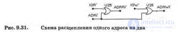
If one air-blast device works only for receiving information (for example, an indicator device), and the second only for transmitting (for example, polling a sensor), then they can be connected to one address, i.e. to one output of the U23 or U24 decoder, using the circuit in Fig. 9.31, in which the address splitting is performed by selection of read-write signals. Elements OR U25, U26 work similarly to U1, U2. In fig. 9.31 ADRi 'is the address signal from the decoder U23 or U24, ADRRi' is the address signal of only the transmitting air-blast, ADRWi 'is only of the receiving.
The IBM PC system bus signals described above belong to the first model of these computers - IBM PC XT. The system bus architecture of such a computer was called XT BUS and is now an integral part of more advanced architectural solutions. Since the IBM PC is essentially a microcomputer that can be used in microprocessor control systems, it seems advisable to provide brief information on the existing architectural solutions for organizing the internal interface of these microcomputers, the descriptions of which are borrowed from the review [22] distributed by FIDO fileecho XHRDDOCS under the name emhwfaqs.zip .
XT-Bus, the XT architecture bus, is the first in the IBM PC family. Relatively simple, supports the exchange of 8-bit data inside a 20-bit (1 MB) address space (denoted as "8/20 bits"), operates at a frequency of 4.77 MHz. The construct is a 62-pin connector (slot).
ISA (Industry Standard Architecture) is the main PC AT bus (also known as AT-Bus). It is an extension of the XT-Bus, the capacity is 16/24 (16 MB), the clock frequency is 8 MHz, the maximum bandwidth is 5.55 MB / s. Separation of IRQs (hardware interrupts) is not possible. Non-standard organization of Bus Mastering is allowed (air-blast with the possibility of autonomous control of the system bus of a microprocessor system), but this requires a programmed 16-bit DMA channel (direct memory access). The construct is a 62-pin XT-Bus connector with an adjacent 36-pin expansion connector.
EISA (Enhanced ISA - Enhanced ISA) is a functional and constructive extension of ISA. Externally, the connectors look the same as for ISA, and ISA cards can be inserted into them, but in the depth of the connector there are additional rows of EISA contacts, and EISA cards have a higher blade part of the connector with additional rows of contacts. Bit depth - 32/32 (address space - 4 GB), operates at a frequency of 8 MHz. The maximum bandwidth is 32 MB / s. It supports Bus Mastering - a bus control mode from any of the devices on the bus, has an arbitration system to control the access of devices to the bus, allows you to automatically configure device parameters, it is possible to separate IRQ and DMA channels.
MCA (Micro Channel Architecture - microchannel architecture) - bus computers PS / 2 company IBM. He is not compatible with any other bus, the resolution is 32/32, (the basic one is 8/24, the rest are as extensions). It supports Bus Mastering, has arbitration and automatic configuration, synchronous (rigidly fixed) exchange cycle duration, maximum throughput - 40 MB / s. Constructive - 1 ... 3-section connector (same as VLB). The first, main, section is 8-bit (90 pins), the second is a 16-bit extension (22 pins), and the third is a 32-bit extension (52 pins). The main section provides lines for transmitting audio signals. In addition, a video extension connector (20 pins) can be installed next to one of the connectors. EISA and ISA are largely identical, the appearance of EISA is due to IBM's ownership of the ISA architecture.
VLB (VESA Local Bus - VESA standard bus) - 32-bit addition to the ISA bus. Structurally, it is an additional connector (116-pin, as in the ISA) to the ISA connector. The resolution is 32/32, the clock frequency is 25 ... 50 MHz, the maximum exchange speed is 130 MB / s; made in the form of an extension of the local processor bus - most of the input and output signals of the processor are transmitted directly to VLB-boards without intermediate buffering. Because of this, the load on the output stages of the processor increases, the quality of the signals on the local bus decreases and the reliability of the exchange through it decreases. Therefore, VLB has a strict limit on the number of installed devices:
at a frequency of 33 MHz on the bus - three, 40 MHz - two, 50 MHz - one, and preferably - integrated (built-in) into the system board (usually port and disk controllers).
PCI (Peripheral Component Interconnect - connection of external components) - the development of VLB with the approach to EISA / MCA. It is not compatible with any others, the resolution is 32/32 (the extended version is 64/64), the clock frequency is up to 33 MHz (PCI 2.1 - up to 66 MHz), the bandwidth is up to 132 MB / s (264 MB / s for 32/32 at 66 MHz and 528 MB / s for 64/64 at 66 MHz), support for Bus Mastering and auto configuration. The number of bus connectors on one segment is limited to four. There can be several segments; they are connected to each other via bridges. Segments can be combined into various topologies (tree, star, etc.). Currently, the most popular bus is also used on other computers. The connector is similar to the MCA / VLB, but slightly longer (124 pins). The 64-bit connector has an additional 64-pin section with its own key. All connectors and cards for them are divided into supporting voltage levels of 5 V, 3.3 V and universal; the first two types must match each other, universal cards are inserted into any slot.
There is also a MediaBus extension introduced by Asustek and containing an additional connector with ISA bus signals.
PCMCIA (Personal Computer Memory Card International Association - an association of manufacturers of memory cards for personal computers) is an external bus for NoteBook computers. Another name for the PCMCIA module is PC Card. Extremely simple, resolution - 16/26 (address space - 64 MB), supports auto-configuration, it is possible to connect and disconnect devices during computer operation. The construct is a miniature 68-pin connector. The power contacts are made longer, which allows you to insert and remove the mother card with the computer turned on. The hardware of the internal interface is performed using a chipset - chipsets.
Chip Set - a set of chips (chipset). This is one or more microcircuits specifically designed to "bundle" a microprocessor. They contain interrupt controllers, direct memory access, timers, a memory and bus management system - all those components that are assembled on separate chips in the original IBM PC. Usually, a real-time clock with a CMOS memory and sometimes a keyboard controller are also included in one of the chipset sets, however, these units can also be present as separate chips. In recent developments, external device controllers began to be included in the chipset for integrated cards.
Externally, the chipset chips look like the largest after the processor, with the number of outputs from several tens to two hundred. The name of the kit usually comes from the marking of the main chip: OPT1495SLC, S1S471, UMC491, 182C437VX, etc. In this case, only the chip code inside the series is used: for example, the full name S1S471 is SiS85C471. The latest developments use their own names; in some cases, it is a company name (Neptun, Mercury, Triton, Viper) or its own marking of third-party chips (ExpertChip, PC Chips).
The type of set basically determines the functionality of the board: types of supported processors, cache structure / size, possible combinations of types and volumes of memory modules, support for power-saving modes, the ability to programmatically configure parameters, etc. Several models of system (motherboard) motherboards can be produced on the same set, from the simplest to the most complex with integrated port, disk, video, etc. controllers.
Test questions and tasks
1. Is it possible to consider a floppy disk drive (floppy disk) as an input / output device? Can the mouse and keyboard also belong to such devices?
2. What is the address space of a computer, how is it distributed in a personal computer such as IBM PC XT?
3. What is the role of the bus driver in the considered air-blast? Design a subcircuit of a bus driver based on a library element with three states (see Fig. 9.16).
4. What control signals of the system bus are the main ones for the air-blast circuit in Fig. 9.28?
5. Conduct all recommended studies for air-blast in Fig. 9.28.
6. Given the desire of developers and manufacturers of IBM PCs to ensure their compatibility from the bottom up, can it be argued that the considered air-blast will work in the latest versions of computers?
7. What type of tires are used in the latest IBM PC versions?

Comments
To leave a comment
Digital devices. Microprocessors and microcontrollers. computer operating principles
Terms: Digital devices. Microprocessors and microcontrollers. computer operating principles