Lecture
The operation of parity control of binary numbers can improve the reliability of the transmission and processing of information. Its essence lies in the summation modulo 2 of all digits in order to determine the parity of the number, which allows you to identify the most likely error in one of the digits of the binary sequence. For example, if the transfer of code 1001 fails in the second category, then at the receiving point we get the code 1101 - such an error is generally difficult to determine. If the code refers to binary decimal (8-4-2-1), then the error is easy to detect, since the received code (the decimal equivalent is the number 13) cannot, in principle, belong to binary decimal.
Error detection by introducing an additional parity bit is as follows. On the transmitting side, the transmitted code is analyzed and supplemented with a control bit to an even or odd number of units in the total code. Accordingly, the total code is called even or odd. In the case of an odd code, an additional bit is formed so that the sum of all units in the transmitted code, including the control bit, is odd. With parity, everything is, of course, the opposite. For example, in the number 0111, the number of units is odd. Therefore, when checking the oddness, the extra bit must be zero, and when checking the parity, it must be one. In practice, the oddity control is most often used, since it allows you to record the complete loss of information (the case of zero code in all information bits). On the receiving side, the parity code is checked. If it is correct, then reception is allowed, otherwise an error signal is turned on or a request for retransmission is sent to the transmitter.
The parity bit generation scheme [8] for a four-bit code is shown in Fig. 9.25. It contains four XOR elements that perform the functions of adders modulo 2 (without hyphenation) and consists of three stages. At the first stage, all bits of the source code at inputs A, B, C, D are summarized in pairs. At the second stage, the signals of the first stage are analyzed and the parity or oddness of the sum of the input code is established. At the third stage, the result obtained is compared with a control signal at input E, which determines the type of control used, as a result of which an additional fifth parity bit is formed at output F, which accompanies the information signal in the transmission channel.

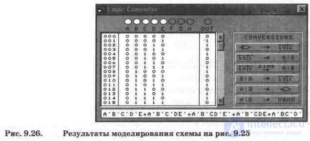
Shaper simulation results are shown in Fig. 9.26 in the form of a truth table of 32 possible binary combinations and a Boolean expression (of the 32 combinations in Fig. 9.26, only the first 16 are visible, the rest are viewed using the scroll bar). To view the components of a Boolean expression, you must use the mouse to place the cursor in the secondary display and move it with the cursor keys.
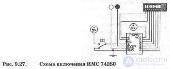
In the library of the EWB program, the parity and oddity check circuit is presented by IC 74280 (analog - K555IP5), the circuit of its inclusion is shown in Fig. 9.27. The IC 74280 has 9 inputs (A, B ... I) and two outputs (EVEN, ODD), one of which is inverse. Input I is used to control the type of control (0 - parity, 1 - odd control) and is controlled by switch Z (controlled by the same key from the keyboard). NC output - not connection - empty, i.e. Inside the IC, nothing is connected to it.
The correct functioning of the circuit in Fig. 9.27 is checked using the word generator, while the type of control (parity or oddness) is selected by the switch Z; various binary combinations are fed to the inputs of the device in question; the state of the IC outputs is monitored by the LEDs connected to them (logic probes).
Test questions and tasks
1. What is the purpose of parity code generators, where can they be used?
2. What form of parity is most often used in practice, in particular, in your computer, if RAM modules with an odd number of microcircuits are installed in it (see Section 5.12)?
3. From the data converter displayed on the screen (Fig. 9.26), select combinations related to parity and oddness control, as well as the corresponding terms of the Boolean expression.
4. Check the correct operation of the circuit in Fig. 9.27, feeding binary inputs from the word generator to the inputs.

Comments
To leave a comment
Digital devices. Microprocessors and microcontrollers. computer operating principles
Terms: Digital devices. Microprocessors and microcontrollers. computer operating principles