Lecture
In the general form of the GSM standard, the time diagram of the transmission process using the TDMA method is as follows (Fig. 2.32):
- An analog speech signal is initially converted to a digital sequence;
- the digital sequence is subjected to encoding, encryption, while using:
a) block coding - to quickly detect errors when receiving signals;
b) convolutional coding - to correct single errors;
c) interleaving - to convert batch errors into single errors.
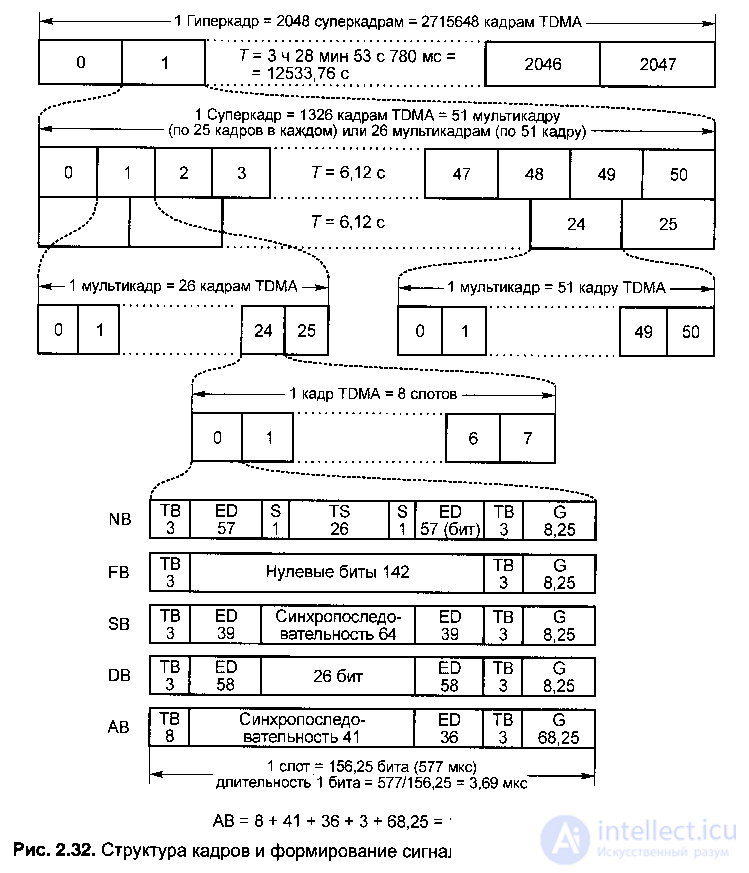
Fig . 2.32. Frame structure and signal shaping in GSM standard (with TDMA)
As a result of these transformations, each sample of the level of the original analog speech signal is represented as an encrypted (encoded) message consisting of 114 bits, which in turn consists of two independent ED information packets (EncriptedData — encoded, encrypted data) 57 bits each (Fig. 2.32). ) in the normal time interval (slot) NB (Normal Burst), separated by a training sequence (26 bits) TS (Training Sequence).
When a sequence is received, the nature of the distortion in the signal propagation path is determined, and the characteristics of the receiver are already formed with reference to specific working conditions at a given time.
For the transmission of information via communication and control channels, adjustment of carrier frequencies, provision of time synchronization and access to a communication channel, five types of time slots are used:
- NB (Normal Burst) - the normal time interval;
- FB (Frequency correction Burst) - time interval of frequency control;
- SB (Synchronization Burst) - time synchronization interval;
- DB (Dummy Burst) - installation interval;
- AV (Access Burst) —access interval.
1) When transmitting over a single voice channel, the GSM standard uses a normal time interval of NB with a duration of 0.577 ms, which includes:
- 114 bits = 57 + 57 - encoded (encrypted) information ED;
- two TV end combinations (TailBits) of three bits each;
- two control bits S (S — StealingFlag — hidden flag) separating the EDs and the employees by a indication of whether the transmitted group contains voice or signaling information. In the latter case, the information channel (TrafficChannel) is “stolen” to provide an alarm;
- TS (TrainingSequence) is a 26-bit training sequence that separates an information block consisting of 114 bits of 57 bits of ED, while using TS provides:
a) an estimate of the frequency of occurrence of errors in binary digits according to the results of comparison of the accepted and reference sequences. In the process of comparison, the parameter RXQUAL, adopted for assessing the quality of communication, is calculated. In this case, we are talking only about the evaluation of communication, and not about accurate measurements, since only part of the transmitted information is checked. The RXQUAL parameter is used when entering a connection, when performing the HANDOVER procedure — a relay transmission and when evaluating the coverage area of a connection;
b) assessment of the impulse response of the radio channel in the NB transmission interval for subsequent correction of the signal receiving path through the use of an adaptive equalizer in the receive path;
c) determining the propagation delays between the base and mobile stations to estimate the communication range. This information is necessary so that data packets from different mobile stations do not overlap when received at the base station. Therefore, remote mobile stations should transmit their packets before mobile stations in close proximity to base stations.
So, the TS training sequence is used to set the equalizer in the receiver in accordance with the characteristics of the communication channel at a given time.
- guard interval G (Guardperiod) with a duration equal to the transmission time of 8.25 bits (8.25x3.69 = 30.44 μs).
Thus, the NB time slot contains 156.25 bits with a duration of one bit equal to 577 / 156.25 = 3.69 μs.
2) The time interval of the FB frequency control is designed to synchronize with the frequency of the mobile station MS and contains:
- 142 zero bits, which corresponds to the unmodulated carrier frequency with a shift (1625/24) kHz above the nominal value of the carrier frequency. This is necessary to test the operation of your transmitter and receiver with a small frequency channel spacing (200 kHz), which is about 0.022% of the nominal frequency of 900 MHz;
- two end combinations of TV, three bits each;
- guard interval G = 8.25 bits.
It should be canceled that repeated time intervals of the FB frequency control form the FCCH frequency setting channel (Frequency Correction Channet).
3) The time synchronization interval SB is designed to synchronize the time of the base and mobile stations. SB consists of:
- synchro sequence of 64 bits;
- two encrypted EDblocks, 39 bits each, carrying information about the TDMA frame number and the identification code of the base station;
- two end combinations of TV, 3 bits each;
- guard interval G length 8.25 bits.
The SB interval is transmitted along with the frequency setting interval.
The repeated time synchronization intervals form the so-called synchronization channel SCH (Synchronizing CHannet).
4) DB installation interval provides the establishment and testing of the communication channel. By its structure, DB coincides with the interval NB and contains:
- 2 blocks of 58 bits each, in which no information is transmitted;
- the installation sequence (instead of TSB NB) with a length of 26 bits;
- 2 TV blocks of 3 bits each;
- a guard interval of G length 8.25 bits.
There are no two control bits S. Since no information is transmitted in the DB, the assignment of the DB is to inform that the transmitter is functioning.
5) AV access interval provides the access permission of the MSk mobile station of the new base station. The AV interval is transmitted by the mobile station MS when the synchronization channel is requested. This is the first packet transmitted by the mobile station, and the signal transit time has not yet been measured.
Therefore, in the access interval, the AVs are sequentially transmitted:
- TV end combination with a length of 8 bits;
- the synchronization sequence for the base station is 41 bits, which allows the base station to ensure the correct reception of the next 36 encrypted bits of the ED;
- 36 encrypted bits;
- 3 bits of TV;
- a large guard interval G, 68.25 bits long (68.25 × 3.69 = 252 μs long), which ensures (regardless of the signal transit time) sufficient time separation from the packets of other mobile stations.
The guard interval of 252 μs corresponds to twice the possible signal delay within one cell and, thus, sets the maximum cell size. For the GSM standard, the ability to provide stable communication for mobile stations in cells is 35 km from BTS MS to a radius, with the maximum propagation time of the radio signal in the forward and reverse directions is -233.3 μs.
Thus, time slots (slots) of NB, FB, SB, DB and AV implement the transmission of various types of information (voice signals, control signals, etc.), which provide both sufficient quality voice transmission and encryption, tuning of the carrier, synchronization, access to the communication channel, etc.
These time intervals and their structure were discussed in the section above on the structure of the Air interface.
In fact:
- NBTDMA is a traffic channel slot;
- FBTDMA is the frequency correction packet slot;
- SBTDMA is a synchronization packet slot;
- DBFDMA is the idle packet slot;
- AV TDMA is an access packet slot.
As in the case of the radio interface, the transmission of information in the time division of channels is carried out as part of a TDMA frame (in the Air-IF frame of the traffic channel).
Each TDMA frame consists of 8 time slots (in an Air-IF frame, a traffic channel consists of 8 slots) with numbers from 0 to 7, that is, 8 voice channels can be simultaneously transmitted in one TDMA frame.
Usually each time slot is denoted by TN with a number from 0 to 7.
The physical meaning of the TN0 ... TN7 positions is the time during which the carrier is modulated by a digital information stream corresponding to a voice message or computer data.
The digital information stream is a sequence of packets placed in these temporary positions TN0 ... TN7, while these packets are formed slightly shorter in time than the time intervals NB, FB, SB, DB, AB (577 micron duration). The length of the TN0 ... TN7 slots is 546 µs, which is necessary for receiving a message in the presence of a time dispersion in the distribution channel.
Since, according to the GSM standard, an informational message is transmitted over the radio channel with a speed of 270.833 kbit / s, the time interval of a TDMA frame contains 270833Х577Х10-6 = = 156.25 bits.
Thus, all time slots NB, FB, SB, DB and AB have the same frame length of 156.25 bits.
Consider further the hierarchical structure of TDMA frames:
- a TDMA frame consisting of 8 slots has a duration of Tk = 577x8 = 4615 μs = = 4.615 ms;
- in the sequence period, each TDMA frame has its own sequence number NF from 0 to NFMax, where NFMax = 26x51x2048 = 2715647 bits;
- TDMA frames are combined into multi-frames of two types:
■ Multi-frame consisting of 26 TDMA frames (in the Air-IF it is the multi-channel of the traffic channel): NF0 ... NF25; the duration of a multiframe of the first type: 26x4,615 = 120 ms;
■ multi-frame consisting of 51 TDMA frames (in the Air-IF it is the multi-channel control channel): NF0 ... NF50; the duration of the second frame - 51x4,615 = 235.385 ms;
- of 51 multi-frames of the first type, a super-frame of the first type is formed, having 26x51 = 1326 TDMA frames, with a duration of 120x51 = 6.12 s;
- of the 26 multi-frames of the second type, a super-frame of the second type is formed, which coincides with the super-frame of the first type in the number of frames and duration;
- the length of the sequence period in the archaic structure, called the hyperframe, is divided into 2048 superframes, that is, by the number of frames in the hyperframe: 2048x1326 = = 2715648 TDMA frames, and by duration T = 12533.76 s = 3 h 28 min 53 s 780 ms.
 The need for such a large period of the hyperframe is explained by the requirements of the cryptographic protection process, in which the NF frame number is used as an input parameter.
Thus, consideration of the structure of TDMA frames and the structure of the radio interface allows us to conclude that their structures are identical.
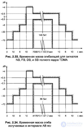
In the GSM structure, the temporal characteristics of the signal envelope (emitted by the packets in the channel time interval of the TDMA frame) and the spectral characteristic of the signal are strictly defined.
The temporal envelope mask for the NB, FB, DB, and SB signals of the full TDMA frame is shown in Fig. 2.33, and the temporal envelope mask for signals emitted in the AV interval of a full TDMA frame is shown in Fig. 2.34.
Different forms of the envelopes of the emitted signals correspond to different durations of the AB interval (88 bits) with respect to other specified intervals of the full TDMA frame (148 bits).
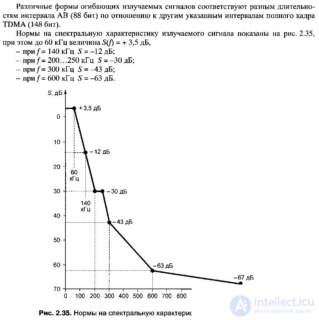
The norms for the spectral characteristic of the emitted signal are shown in Fig. 2.35, with up to 60 kHz S (f) = + 3.5 dB,
- at / = 140 kHz S = -12 dB;
- at / = 200 ... 250 kHz S = -30 dB;
- at / = 300 kHz S = -43 dB;
- at / = 600 kHz S = -63 dB.
Frequency jumps One of the features of the formation of signals in the GSM standard is the use of slow jumps in the frequency of SFH (Slow Frequency Hopping) during a radio communication session. The main purpose of these jumps in frequency is to provide frequency diversity in radio channels operating in conditions of multipath propagation of radio waves. SFHs are used in all mobile networks, which increases coding and interleaving efficiency when subscriber MSs are slow. The principle of forming slow jumps in the SFH frequency is that the message transmitted in the time interval of the TDMA577 μs frame allocated to the MS subscriber is transmitted (or received) in each subsequent frame at the new fixed frequency (Fig. 2.36), that is, if the MS initially transmitted at the frequency / * (TN0), when moving in time, the frequency changes to fj (TN0), then to / (TNO), etc. In accordance with the structure of TDMA frames, the time for frequency tuning is 1 ms (in this case, the time of the frequency jump will be determined —0, 577 * 8 = 4.616 ms). In the process of jumps in frequency, the duplex separation of 45 MHz is constantly maintained between the receive and transmit radio channels (Fig. 2.37) |

All active MS subscribers located in the same cell are assigned orthogonal forming switching sequences, which eliminates mutual interference when receiving messages by MS subscribers in a cell.
The parameters of the sequence of switching frequencies (frequency-time matrix (Fig. 2.36) and the initial frequency) are assigned to each mobile station MS in the process of establishing a communication channel. The orthogonality of sequences of switching frequencies in a cell is provided by the initial frequency shift of the same (according to the algorithm of formation) sequence.
Adjacent cells use different shaping sequences. The combined TDMA / FDMA channel organization scheme in the GSM standard and the principle of using SFH when transmitting messages in time frames were shown in Fig. 2.36 and fig. 2.37.
Thus, if we take into account that in the frame each physical channel corresponds to one slot, then for any of the physical channels this frequency of jumps is equivalent to changing frequency channels with the frequency of slots.
SFH operation mode assigned by MSC switching center

Comments
To leave a comment
GSM Basics
Terms: GSM Basics