Lecture
The GSM mobile network is a large and complex telecommunications system.
Different user groups have access to its resources:
- mobile network subscribers;
- fixed telephone network subscribers (PSTN);
- subscribers of digital communication networks;
- GSM network maintenance operators, etc.
When considering the internal organization of a GSM network as a telecommunication system, several components of its subsystems should be distinguished (Fig. 2.11):
- MS (MobileStation) - mobile stations (mobile phones) used by users of the mobile network;
- BSS (Base Station Sub-System) - subsystem base stations;
- NSS (Network and Switching Sub-System) - network commutation subsystem;
- NMS (Network Management Subsystem) - network management subsystem. 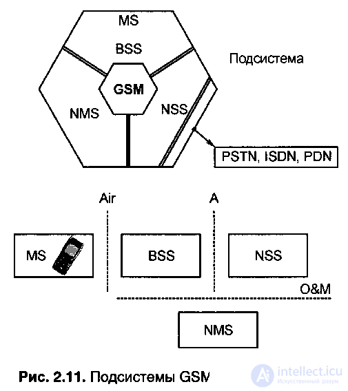
When sending messages, adaptive power control of the MS transmitter is provided, providing the required quality of communication.
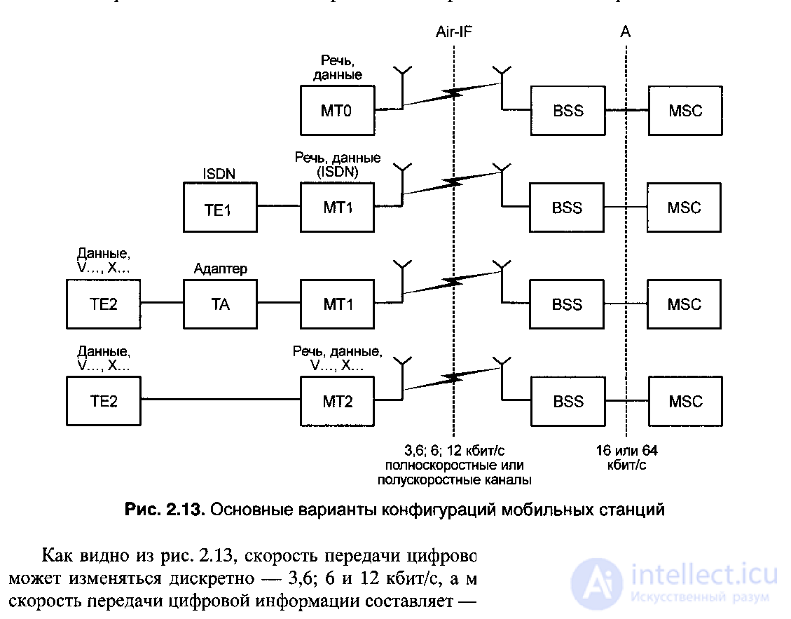
Mobile stations can access GSM network resources using the air interface (Air-interface) through the BSS subsystem, or more precisely through the BTS (Base Transceiver Station) - base transceiver stations, which are located approximately in the centers of the respective cells. In general, you can point to four basic configuration options for mobile stations (Fig. 2.13):
1) Mobile Termination (MTO) is a functionally complete mobile station, including a network terminal and terminal equipment (i.e. a mobile phone), which allows voice and computer data (data) to be transmitted and connected to the BSS using the Air-interface radio interface.
2) MT1 (Mobile Terminal 1) is a mobile terminal that allows voice and data transmission from the ISDN network to the GSM cellular network, supporting the TE1 terminal equipment (TE - TerminalEquipment) with an ISDN network interface.
3) MT1 (Mobile Terminal 1) - a mobile terminal that allows you to transfer data from computer networks via CCITT interfaces
V series ... or X series protocols ... (for example - V.24, X.21, X.25), through the TA terminal adapter (TA - TerminalAdapter), that is, the TE2 terminal equipment is connected via the TA terminal adapters to the mobile terminal MT1.
4) MT2 (Mobile Terminal 2) is a mobile terminal that allows you to transfer data from computer networks to the GSM network through TE2 without a TA terminal adapter.
 |
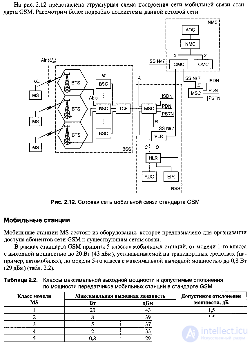
The BSS base station subsystem includes:
- BTS — Base transceiver stations located in the respective cells and allowing radio communication with MS mobile stations within the cell via the radio interface over the radio channels, in accordance with the selected frequency reuse model in cells. The radio interface equipment (Air-Interface or Um-Interface) provides the transmission and reception of voice signals and data over the MS BTS radio path;
- BSC (Base Station Controller) - a base station controller, one or more, depending on the number of BTS, determined by the territory served by the GSM operator, and on the volume of call flows (telephone load) of each BTS. The base station controller is a fairly powerful and sophisticated computer that provides BTS operation control and monitoring the performance of all BTS units. In particular, the BSC manages the radio interfaces between the MS and the BTS, as well as a procedure such as a handover (the radio and fixed channels involved in a GSM call are not tied to this call, which makes it possible to move the mobile subscriber from cells per cell in the call process, which is called handover);
- standard for interface connection BTS with BSC, more precisely BSC with each BTS received the interface name A-bis.
So, BSC implements the following main functions:
- management of radio resources of one or several BTS (the number of BTS is mainly determined by the volume of call flows (telephone load), for example, in a densely populated area there can be a large number of BTS connected to several BSCs);
- control of the radio channel;
- channel frequency adjustment;
- call management (handovers) moving from cell to cell by mobile stations, with the BSC being the link between the MS and the MSC;
- TCE (Trans Coder) - transcoder, provides conversion of the output signals of the voice channel and MSC data (64 kbps with PCM (pulse code modulation)) to the form that corresponds to the GSM recommendations over the air interface (recommendations GSM 04.08). In accordance with these requirements, the transmission rate of speech signals, represented in digital form, is 13 kbps. This channel of voice transmission in digital form is called full-speed.
The GSM standard provides for the use of a half rate voice channel with a transfer rate of 6.5 kbps.
Network and switching subsystem NSS
The network and switching subsystem NSS of the GSM network provides switching functions and contains databases necessary for managing subscriber mobility and ensuring communication security (that is, preventing unauthorized use of the GSM network and ensuring the privacy of subscribers). The main function of the NSS is to manage the processes of connecting mobile GSM subscribers between themselves and with subscribers of fixed networks. The NSS subsystem consists of the Mobile Switching Center (MSC), a mobile switching center.
In any cellular mobile communication network, the switching center is a think tank and at the same time a control center of a cellular communication system, to which information flows from all base stations are locked and through which access to other communication networks: fixed telephone network (PSTN), long-distance communication network, satellite communications and other networks, including other cellular mobile networks. Typically, the switching center includes several processors (controllers), and it is a typical example of a multiprocessor system. The block diagram of the switching center is presented in Fig. 2.14.
 Fig. 2.14. Block diagram of MSC switching center |
The switch itself switches the flow of information between the respective communication lines. It can, in particular, direct the flow of information from one BTS to another, or from a base station to a fixed (fixed) communication network, or vice versa - from a fixed communication network to the desired base station. The switch is connected to the communication lines (usually to fiber-optic lines) through appropriate communication controllers, which carry out intermediate processing (packing / unpacking, buffer storage) of information flows. The overall control of the switching center and the system as a whole is carried out from the central controller, which has powerful mathematical software, including the reprogrammable part.
The work of the switching center involves the operational participation of operators, therefore, the switching center includes appropriate terminals, as well as means of displaying and recording information. In particular, the operator enters data about the subscribers and the conditions of their service, initial data on the mode of the system, in necessary cases, the operator issues requiring commands in the course of the work.
Important elements of the switching center are databases:
- home register or location register HLR (Home Location Register);
- guest register or VLR movement register (Visitor Location Register);
- AUC (Authentication Center) authentication center;
- register equipment EIR (Equipment Identity Register).
In general, the HLR register contains information on all mobile subscribers registered in this cellular mobile communication system, on the types of services that can be provided to them (when concluding a service contract for different subscribers, it can be provided, generally speaking, to provide a different set of services) . In HLR, the subscriber’s location is fixed for the organization of his call and the actually rendered
The VLR register contains approximately the same information about guest subscribers (roamers), that is, subscribers registered in another cellular mobile system (another mobile operator), but currently using cellular services in this system (for example, registered in the LMT cellular network, while in Germany, talking on a mobile phone with an LMT subscriber in Latvia, the VLR register of the GSM network in Germany provides all the services of this network, subject to the existence of roaming agreements between mobile operators, i.e. LMT — operator in Germany).
AUC provides a procedure for authenticating and encrypting messages.
The hardware register (more precisely, the hardware identification register), if it is used in a cellular network, contains information about the mobile stations in use for their health and authorized use. In particular, it may indicate stolen mobile devices, as well as devices that have technical defects, for example, are sources of interference to an unacceptable level.
As in base stations, switching centers usually provide for redundancy of basic hardware components, including power supplies, processors and databases.
Turning specifically to the GSM MSC standard, we note the following.
1) As a rule, when organizing a GSM network, one or two MSCs are used in an area where up to 1 million users live (maybe even possible).
2) The equipment of one MSC is placed in 4-6 cabinets, while the basic functional blocks of the MSC are duplicated.
3) The main functions performed by the GSM MSC standard include:
- providing services to a group of cells and all types of connections that mobile stations need in their work;
- providing call routing and call control functions;
- the interface between the mobile communication network and fixed networks, such as the PSTN (Public Switched Telephone Network) - telephone (fixed) public network; ISDN (Integrated Services Digital Network) - a digital network with integrated services; PDN (Packed Data Network) - packet data switching network; PSPDN (Packet Switched Public Data Network) - packet switched data network; Circuit Switched Public Data Network (CSPDN) - circuit-switched data network;
- implementation of switching of radio channels, which include a relay transmission, which ensures continuity of communication when mobile stations move from cell to cell and switching working radio channels in a cell when interference or malfunction occurs;
- implementation of constant tracking of mobile stations using registers: HLR — location register and VLR — register of movements (walks) of mobile stations.
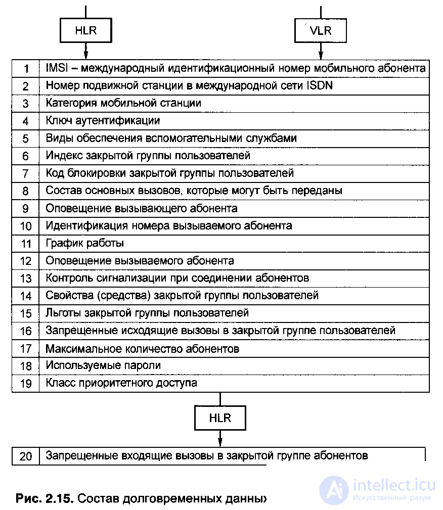
HLR — Mobile Subscriber Location Register. It is a computer database of subscribers - mobile users. The HLR stores that part of the location information of any mobile station that allows the MSC switching center to place a call to this station. HLR contains the following long-term and temporal data, which are summarized in tables of Fig. 2.15 and fig. 2.16.
As follows from fig. 2.15 and 2.16, the HLR register contains:
- the international identification number of the mobile subscriber IMSI (International Mobile Subscriber Identity), necessary to identify the mobile station in the AUC authentication center;
- Mobile station number in the international ISDN network;
- Basic information about all subscribers of mobile stations (3, 4, 8, 9, 10, 12, 13, 17, 18,19);
- list of additional communication services available to the mobile subscriber;
- specific information on the routing of incoming calls;
- registration of data about roaming (roaming - wandering) of mobile subscribers.
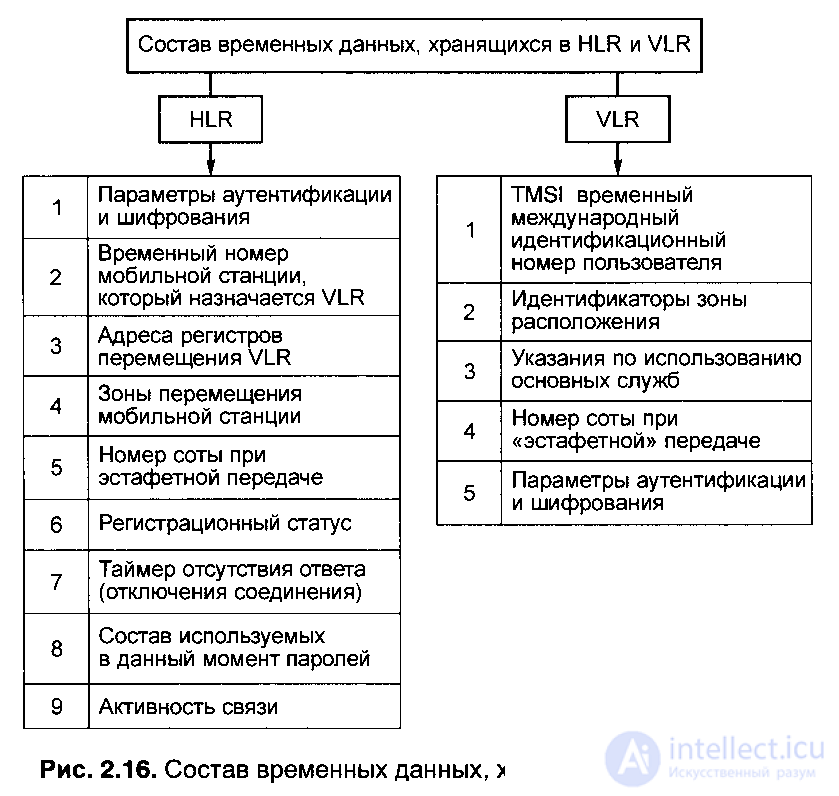
In this case, the HLR records information about the temporary identification number of the mobile subscriber TMSI (Temporary Mobile Subscriber Identity) (Fig. 2.16) and in the VLR register. TMSI is assigned to each mobile subscriber of the GSM network in order to exclude its detection (detection) by intercepting the transmitted message (that is, ensuring communication security). A specific TMSI is valid only within a certain local LA zone (Fig. 2.17).
In the mobile network of the GSM standard, cells are grouped into geographical local zones LA (Locations Areas). Each LA has its own identification number - LAI (Location Area Identity). Each VLR register contains data on mobile subscribers located in several geographical areas of LA.
If the mobile subscriber moves from one LA1 zone to another LA2, then its location data is automatically updated in the VLR, and the current VLR address for that subscriber in the HLR register is also updated.
If the zone of the previous location of the subscriber LA1 and the zone of its current location LA2 are controlled by different VLR location registers, that is, LA1 - in VLR1, aLA2 - in VLR2, then the data in the register (previous register) VLR1 about the MS subscriber is automatically erased, but only after copying them into VLR2 of the LA2 zone (the current VLR address (that is, VLR2) for this subscriber contained in the HLR register is also updated). Returning to the temporary TMSI subscriber identification number, as shown in Fig. 2.17, TMSI1 is valid only within the local zone LA1 of the current location of the subscriber, when the mobile subscriber moves to the zone LA2, it is assigned a new TMSI2 (VLR2). All this TMSI information is transferred from VLR1 to VLR2, etc.

Comments
To leave a comment
GSM Basics
Terms: GSM Basics