Lecture
In fig. 5.2 shows the structural diagram of the base transceiver station in the subsystem BSS.
The main features of the base station BTS (Fig. 5.2) include the following:
- An antenna system consisting of two separated antenna devices, while switching the receive / transmit mode of the antenna using an electronic switch; 
- the presence of several receivers and the same number of transmitters that allow simultaneous operation on several channels with different frequencies;
- like receivers and transmitters of the same type have common tunable reference oscillators, ensuring their consistent restructuring when switching from one channel to another;
- simultaneous operation of N receivers on the antenna system in the reception mode and on N transmitters in the transmission mode is ensured, respectively, by a divider and adder that, in the case of reception, realize the division of the received signal power into N inputs, and in the case of transmission - summation of output powers from N outputs ;
- BTS receivers and transmitters have the same structural scheme as in mobile stations, except that they do not have ADC and DAC, since the input signals of the transmitters and the output signals of the receivers are digital;
- the interface unit with the communication line implements the packaging of digital information transmitted via the communication line to the BSC controller and then to the MSC switching center, and unpacking the digital information received from it;
- MSC and BSC provide control of the operation of all BTS in the service area, as well as monitoring the performance of all BSS units and nodes.
In the GSM standard, a certain number of BTS are connected to the BSC (up to sixteen BTS per BSC). Depending on the antenna system used in BTS, three variants of BTS are possible (Fig. 5.3):
BTS omnidirectional antenna system providing uniform radiation within a cell (omnidirectional BTS);
BTS antenna system, when antennas with 120 ° radiation patterns in the azimuth sector within a cell, i.e. 3 areas of radiation and reception (3 sectorized BTS) are used in BTS;
in one BTS there are 6 sectors (60 ° each) (6 sectorized BTS).
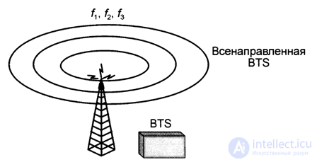
Omnidirectional BTS
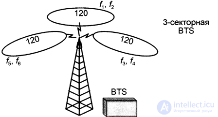
3 Sector BTS
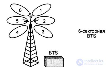
6 Sector BTS
Fig. 5.3. Three variants of BTS antenna systems
In fig. 5.4 shows a typical BTS tower with an antenna system (two vibrators separated by d <2 m (d / X ~ 5) for mobile communication, two antennas for radio relay communication, in addition, Fig. 5.5 shows the appearance, and Fig. 5.6 equipment internal layout in a hardware communication container where GSM equipment is installed for GSM 900, 1800, NMT-450 standards, air conditioner, RRL radio link equipment, power supply and alarm system.
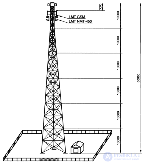
Fig. 5.4. The appearance of the tower and the hardware container BTS
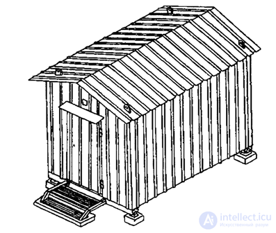
Fig. 5.5. Appearance of the BTS hardware container
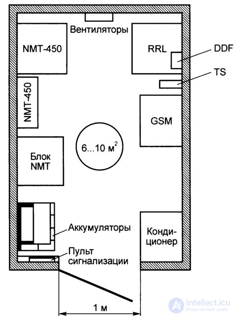
Fig. 5.6. The internal layout of the GSM and NMT-450 hardware in the BTS communications container container
The height of the BTS antennas varies widely:
- on buildings - from 20 to 40 m;
- on the towers - discretely - 45, 50, 60, 72,100 m.
Typically, the power values of the BTS transmitters are of the order:
- GSM 900 - L ~ 50 ... 55 W;
- GSM 1800 - Pt ~ 12 W.
The gains of the BTS antennas are Gt —50 ... 55 dB.

Comments
To leave a comment
GSM Basics
Terms: GSM Basics