Lecture
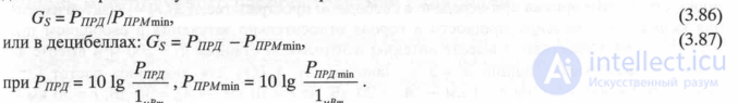
Under the gain of the radio communication system understand the ratio of transmitter power to the threshold sensitivity of the receiver:

Maximum service area.
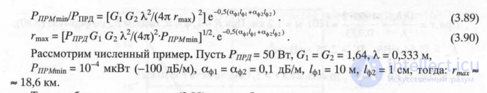
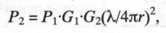
The expression for the radio range rmax (or the maximum distance at which service can be performed during propagation of radio waves in free space within the line of sight) can be obtained from the expression:

Thus, the expression (3.90) can be used for estimating calculations of the maximum cell radius for highly raised antennas during propagation of radio waves within the line of sight.
Calculation of the median value of the received signal power.
To calculate the median value of the signal power received by the antenna of a mobile station in an urban environment, you can use the following equation, in which all values are given in decibels (dB) [3.6]:


Model of multipath propagation of radio waves.
The propagation model, standardized by Group Special Mobile, was developed for the global digital cellular network [3.4] standard, with the proposed scheme of the multiple-pass simulator of Rayleigh / Raiss fading (Fig. 3.18).

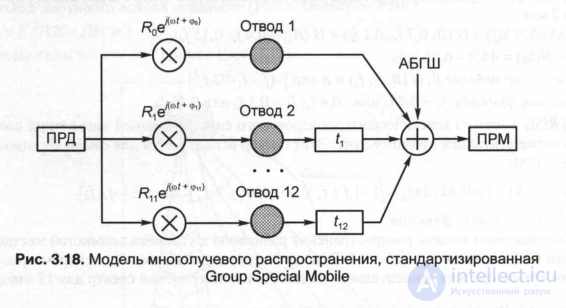
where Rt is the amplitude of the envelope of the high-frequency signal, cf, its phase and m, is the scattering time of the radio signal envelope, RA is the white Gaussian noise.
In the GSM simulator, shown in Fig. 3.18, for each tap, the conditions for the propagation of electromagnetic waves on the indirect visibility path (NLOS — Not Line-Of-Sight) are determined with amplitudes distributed according to Rayleigh's law, varying in accordance with the Doppler spectrum. A separate line of sight [LOS - Line-Of-Sight] is modeled using the Raissian distribution function. For GSM systems, four types of Doppler spectra are specified, which are used to simulate and test GSM systems [3.4]:
1) CLASS - classic Doppler spectrum, which can be used for paths with delays not exceeding 500:
 The level of electromagnetic radiation antennas BTS within the cell.
Consider the simplest method of numerical calculation of the power flux-density as a function of the distance from the transmitter antenna of the base station, given: elevation of the antenna (h {), radiation pattern Fi (0), antenna gain Gb, attenuation multiplier W and reception point height (hi ). Suppose that in the first approximation the calculation of the electric field strength at the point of reception will be carried out for the single-beam model, then the effective values of the electric field strength (with vertical polarization) and directional properties F (0) = sin0 of the antenna of the base station,
with F (89.51 °) = 1, it will be written:

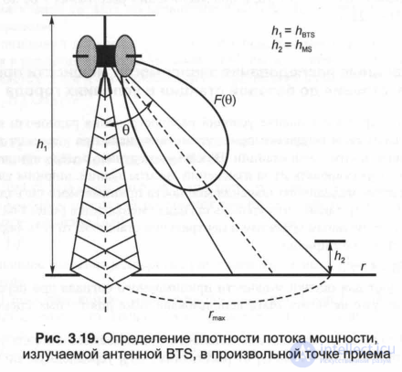
Fig. 3.19. Determination of the power flux density radiated by the BTS antenna at an arbitrary receiving point

Experimental studies of the dependence of the received signal power on the distance to the base station in the city
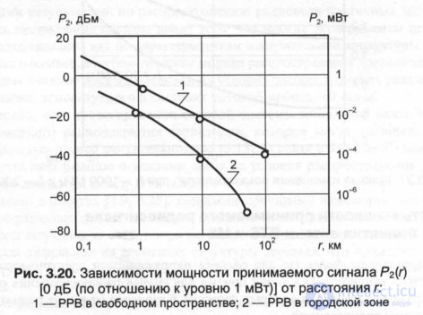
One of the main problems in assessing the propagation conditions of radio waves is the description of the processes of attenuation of the received signal power when the receiving station is removed from the transmitter of the central station. In the real case, the level of the received signal will fluctuate noticeably due to changes in the height of buildings, the width of streets and the nature of the terrain. The behavior of the median power of the received signal, as shown by experiments [3.7–3.9], is such that the signal level decreases more rapidly than the distance between the mobile object and the central station increases, that is, the formula for determining the power at the receiving point:
 (3.103)
which is used to estimate the power of the received signal during transmission in free space, can no longer be used even for rough estimates in urban environments.
In fig. 3.20 shows the dependence of the received signal power [with respect to the level of 0 dB (relative to 1 mW)] on the distance P2 (g), averaged over the experiments

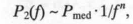
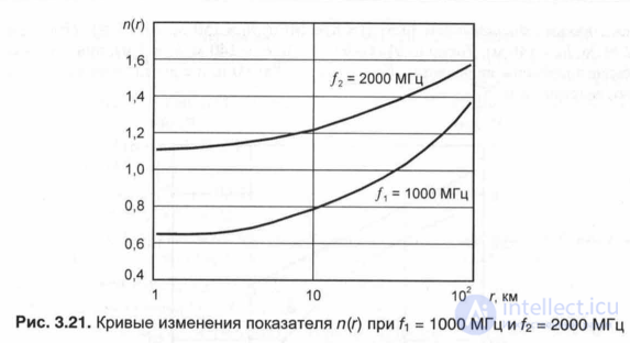
The change in attenuation of the received radio signal depending on the operating frequency of the BTS.
In urban conditions, the attenuation of the signal increases with increasing operating frequency. The dependence of the received signal power on the distance at a constant height of the transmitting and receiving antennas has the character [3.6]:


The dependence of the received radio signal power on the height of the BTS and MS antennas.
Above, formulas were given for calculating the electric field strength Eg and the power flux density P at the reception point for the case of propagation of radio waves over the flat surface of the earth, in which the function F depended on the antenna heights of the base and mobile radio stations.
Power losses during transmission over a flat earth's surface are approximately described by the relation [3.15]:
 .
.

Comments
To leave a comment
GSM Basics
Terms: GSM Basics