Lecture
GMSK (Gaussian Minimum Shift Keying) - Gaussian modulation (more precisely, manipulation) with a minimum frequency shift (shift keying) used in the GSM standard, is essentially nothing more than binary digital frequency modulation (FM) with Gaussian prefiltration (Gaussian filter band is B = 81.3 kHz).
As you know, frequency modulation is the most commonly used type of analog modulation. A digital FM has been developed for data transmission, known as FSK (Frequency Shift Keying). The FSK modulation index can be set in advance and determines the narrowband or wideband mode. Simple non-coherent demodulators can be used to demodulate a large class of signals with FSK. However, such demodulators require a higher carrier-to-noise power ratio (CNR - Carrier-to-Noise-Ratio) than for systems with coherent demodulation.
If the transmitter frequency deviation is carried out according to the expression [4.1]:

where Tb is the bit length of the input digit of the sequence (with m4M = Afpp Tb = 1/2), then coherent modulation / demodulation of signals with a minimum frequency shift MSK (Minimum Shift Keying) can be implemented.
In fig. 4.16 shows the possibility of obtaining frequency modulation using a voltage-controlled frequency generator (VCO).

Fig. 4.16. Frequency modulation using voltage-controlled frequency oscillator (VCO)
The logical state “1” corresponds to the frequency / 2, and the logical state “O” (the voltage level of the digital data U0 = -1V) - the frequency / i.
The frequency deviation for coherent FSK is determined by the expression (4.1), while between the transmitted frequencies and the bit rate, it is necessary to ensure the coherence ratio, which corresponds to the frequency modulation index, defined by the expression:

As the name of GMSK modulation suggests, in essence, the term “Gaussian” corresponds to additional filtering of the spectrum of the modulating bit sequence with a relatively narrow-band Gaussian filter having a response to rectangular pulses at BT-0.3 (Fig. 4.17).

Fig. 4.17. The response g (f) of a Gaussian filter to a rectangular pulse at a value of Tb = 0.3:
B - Gaussian filter band at 3 dB, Tb - bit duration)
So, the Gaussian narrow-band filter used in GSMK modulation of the GSM standard has the parameters: the product of the band by the duration of one bit is - BT = 0.3; With BT => oo, this value corresponds to MSK. Smaller VT values lead to a more compact spectrum, but also to an increase in the level of distortion.
Therefore, the value of BT = 0.3 was chosen from compromise considerations: a sufficiently high spectral efficiency (that is, the efficiency of using the B frequency band, (bit / s) / Hz, which for GSM is equal to 1.35) and the required characteristic of the probability of error per bit ( that is, the BER values - the threshold error probability per bit), which for adaptive delta modulation codecs may allow BER ^ 10-2, and for PCM systems - BER ^ 10-4.
For a more detailed study of the GSMK modulation method, consider the MSK method, and then consider the effect of a Gaussian filter on the resulting modulating signal.
MSK method
The MSK method is usually considered as a quadrature phase shift keying method with offset OQPSK (Offset Quadrature Phase Shift Keying) [4.1, 4.4], but replacing (in MSK) rectangular modulating pulses [(duration 2T) in OQPSK] by half-wave segments of sinusoids or cosine waves ( Duration also 2T).
Consider the block diagram of the modem (modulator / demodulator) MSK, shown in Fig. 4.18 [4.1].

Fig. 4.18. MSK Modem Circuit
It should be noted that in the scheme (Fig. 4.18) the following notation is used:
® - multiplier (balanced modulator or signal processor);
MS - generator of unmodulated carrier frequency (/ o);
FV at 90 ° - phase shifter at 90 °; ® - adder that implements the summation (more precisely, the subtraction) of the two terms of expression (4.6); FI - pulse shaper;
Sun - input signal.
MSK modulator
1. Get a quadrature representation of the FSK signals as applied to MSK.
The frequency-manipulated signal Sfsk (0 can be considered as a harmonic signal (sine or cosine), the frequency of which can take two values:

2. In fig. 4.18 in the MSK signal modulator circuit, its terminal part implements expression (4.6): the signal of an unmodulated carrier frequency / o is multiplied (for this, a nonlinear mode is selected in the balanced mixer, allowing multiplication) with the common mode
The further process of generating the MSK modulating signals is described above in § 1-4 of this paragraph.

Fig. 4.19. Signal timing and phase modulation at MSK
The width of the main lobe of the MSK signal spectrum is ± 3/4 TV, that is, when the duration of one bit is equal to TV = 3.69 μs, the frequency band is fn = ± 0.2 MHz, while the spectrum of the unfiltered MSK signal decreases proportionally to / 4.
MSK demodulator
After passing the high frequency path with double conversion of the carrier frequency (see Fig. 4.2), the signal along with the noise enters the MSK demodulator (see Fig. 4.18) and enters along three circuits, including:
- two circuits in the multiplication scheme for two I (t) and Q (t) quadrature signals;
- a circuit in the EAS unit (carrier recovery circuit).
The CBH scheme generates the recovered carrier signals / = / 0 ± A / to the multipliers, using the delay of 90 ° in the signal phase shifter to then form the quadrature signal Q (t).
After the multipliers, signals I (t) and Q (t) are formed, which are then passed through receiving filters (PFP / F), which can be used as low-pass filters (LPF).
The signals I (t) and Q (t) then arrive:
- in threshold decision schemes (ORS);
- to the clock recovery circuit (SCTC).
The SVTC circuit outputs signals to the PRS for tightly binding the entire demodulator at the clock frequency of the digital sequence Ts and from the PRS inputs to the 2 SPP inputs, as well as signals from the SVTPCH circuit generate signals from the regenerated quadrature signals I (t) and Q (t), and combined in a serial-to-parallel converter to get the original digital sequence.
Modem (modulator / demodulator) GMSK
The GMSK modulator differs from the MSK modulator only in that the pre-modulation Gaussian low-pass filter (GFNCH) with the amplitude-frequency characteristic in the form of a Gaussian curve (see Fig. 4.17) is included in the SPT circuit, which leads to the following change in MSK:
- the width of the main lobe and the levels of the side lobes of the spectral density (formula (4.10)) decrease, which leads to an increase in the spectral efficiency of the modulator;
- the use of GFNC smoothes the dependence of the phase on the magnitude (PTV) during phase-frequency manipulation in MSK;
- the choice of the GFNCH band equal to B »0.3! TV for GMSK allows, on the one hand, to narrow the spectrum of the digital signal, and on the other, increases the level of intersymbol distortion (i.e., the overlap of characters on each other).
Consider the frequency and impulse characteristics of the HCFN. The input BFNS fed digital signal flow BVN (NRZ):
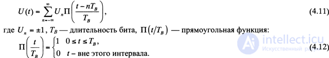
The frequency and impulse characteristics of HFNC are defined by the following expressions [4.1]:

In fig. 4.17 shows the impulse response of the HFNC for the HTB values: for HTB = 0.3 and VTB -> 00.
Thus, the GMSK modulator is a compound of the GFNC and the MSK modulator.
In coherent demodulation of signals with GMSK, as in MSK, a quadrature structure similar to the signals with OQPSK is used, while the demodulated quadrature low-frequency signals I \ t) and Q \ t) are described by the functions cosqp (f) and sincp (f), respectively.
The quadrature representation of the modulated GMSK signal is as follows [4.1]:

With the use of a pre-detector bandpass filter (DDPP) (especially Gaussian DCPP) with B {Guv a 0.63, coherently demodulated low-frequency components cos [qp (f) l and sin [(p (f) l) contain significantly less components of intersymbol distortions .
The finally digitally demodulated stream, passing the low-pass filter, falls in accordance with the scheme of Fig. 4.2 to the channel equalizer input.
Concluding consideration of the GMSK modulation, a number of important advantages should be noted:
1) a sufficiently high spectral efficiency (bandwidth efficiency), equal to: 270.883 / 200 = 1.354 (bit / s) / Hz, due to the use of LFNC with HTB = 0.3;
2) low interference on adjacent frequency channels;
3) noise immunity acceptable for practice: probability of error per bit Рс а 10_3 at carrier / noise ratio C / N = 30 dB;
4) the possibility of using coherent and incoherent demodulation;
5) high efficiency of the transmitter power amplifier (due to the use of a non-linear amplifier NLU).
GMSK modems are used both in the GSM standard and in other European standards.
Currently, there is a technical implementation of the GMSK modem in the form of a single-chip VLSI [4.1]

Comments
To leave a comment
GSM Basics
Terms: GSM Basics