Intersymbol distortions in the transmission of digital signals arise mainly due to the appearance of the path differences between the reflected radio waves during their multipath propagation.
The desire to reduce, compensate for these distortions led to the development of an equalization method - equalizing, the meaning of which is to compensate for the difference in the path between the component rays in multipath propagation of radio waves, which leads to intersymbol distortions.
The equalizer (<equalizer) is inherently an adaptive (adaptive) filter that is configured so that the signal at its output is cleared as much as possible from the intersymbol distortion contained in the received input signal. The simplest implementation of an equalizer is shown in Fig. 4.20.
> BUY REPITER - CDMA / GSM / DCS / WCDMA ...
The equalizer in this scheme represents a transversal filter, similar to that which can be used in a speech coder, but with a fundamentally different tuning algorithm.
Consider the principle of operation of the circuit Fig. 4.20 and show the conditions of partial attenuation of only one additional signal (from multipath we choose: the main beam and one interfering signal, called a copy of the main one, but whose radio wave is shifted in time by m = TV - the duration of one bit).

Fig. 4.20. Linear equalizer based on a transverse filter with a three-element delay line under the following conditions: tz = TV, Ci = 1/3, C2 = 1/9, Cz = 1/27) [4.4]
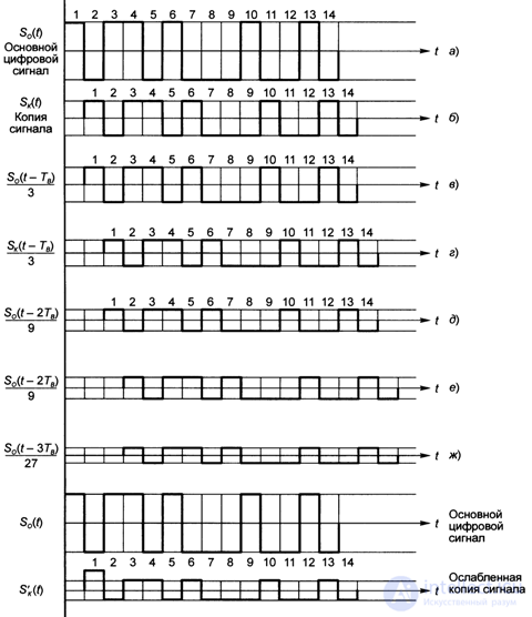
In fig. Figure 4.21 shows a timing diagram of signals sequentially propagating along delay lines and multipliers.
one. Let the input equalizer (Fig. 4.20) receives two signals:
- the main digital signal So (t),
- copy of the signal S0 (t) - SK (t), shifted in time by tx = Tv (the duration of one bit).
These two signals are fed to the input of the first delay line (JI3) and to the input of the adder.
2 With the passage of the first delay line (JI31) and after multiplication with the signal Ci = 1/3, the main signal turns into So (t - TV) / b (c), and interfering into S ^ t - TV) / b (d).
3 With the passage of the second JI32: the main signal shifts by 2Tv and decreases in magnitude by C2 = 1/9 times, that is, S0 (t - 2Tv) / 9 (E), and the copy of the signal: S ^ t - 2Tv) / 9 (e ).
four. With the passage of the third JI33: the main signal shifts by 3TV and decreases in magnitude by C3 = 1/27 times, and the copy of the signal, which had values 1 and 0 not so large, is not shown in the figure, 5 / s (* -TB) / 21 “SK (t - 2Tv) / 9.
five. Thus, the adder receives 6 signals that are shifted in time by the values of At = pTv, and as a result of their summing, the output is:
- main digital signal S0 (t),
- weakened copy of the signal (interference), starting from the moment of time t \ = 2TV and further along the time scale.
So, in the considered equalizer scheme, adding each next element of the delay line with the corresponding coefficient value leads to a threefold weakening of the distorting signal and to an additional delay in time by m.
This equalizer scheme is built on the basis of a transversal filter and is linear, as is the corresponding scheme with a trellis filter.
Such a linear equalizer is quite simple in structure, but it has drawbacks that appear with large signal distortions.
In real conditions, everything is much more complicated than in the above example.
The number of rays is naturally more than two, the delay of the rays is unlikely to be a multiple of the JI3 discrete, and the amplitudes of the interfering signals cannot be predetermined or known. In addition, when moving MS, the whole picture of fig. 4.21 will continuously change.
Therefore, the adjustment of the equalizer filter should be made adaptively, in accordance with the changing situation, separately for each speech segment transmitted in one slot of the radio interface, using the learning sequence transmitted in each slot.
Fig. 4.21. Timing diagram of signals sequentially propagating along delay lines and multipliers in the equalizer
The simplest transversal filter tuning algorithm that minimizes the root-mean-square error at its output is the stochastic gradient algorithm, according to which the filter coefficients vector C is updated as a result of the sequential application of the recurrent procedure [4.4]:

the symbol and its estimate at the output of the filter, \ x is the proportionality coefficient (step size), which determines the rate of convergence of the iterative process and the stability margin. Algorithm (4.23) has a slow convergence.
In practice, the recursive algorithm for the minimum of the root-mean-square error, and, in particular, its computationally efficient modifications that provide a higher rate of convergence, is more convenient.
A more detailed and detailed presentation of the material about equalizers can be found in [4.9, 4.10].
In conclusion, consideration of equalizers should be noted that nonlinear equalizers are more advanced [4.4]:
- solution feedback scheme;
- maximum likelihood symbol detection scheme;
- the scheme of the most plausible sequence evaluation, etc.
If in the first scheme transversal and lattice filters can be used, in the second and third - transversal.
The total length of the delay line of the filters must correspond to the difference in the path of the rays for which it is desirable to compensate for distortion, and the discrete delay line (i.e., m3) must be less than the symbol duration.
The equalizer unit is part of the receiver (see Fig. 4.2) and its device does not affect the composition and presentation of information transmitted over the radio interface and TDMA frames.
Therefore, the scheme and characteristics of the equalizer are not only not regulated by any standards, but in general the equalizer unit may not be included in the receiver path.
The choice of the equalizer circuit and its inclusion are solely the business of the manufacturer.

Comments
To leave a comment
GSM Basics
Terms: GSM Basics