Lecture
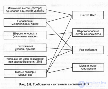
One of the important elements of the equipment in cellular mobile communication systems is the antenna system used in the BTS to create a uniform radio coverage of the cell (or sector within a cell), stable reception from mobile stations (while minimizing interference), determining the location of MS, etc. Therefore, the requirements for BTS antennas are quite high, both in terms of hardware parameters and the technology of antenna systems (Fig. 3.8).
In normal operating cellular systems, the power gain due to the use of BTS antennas is from 7 to 15 dB. The following requirements must be met:
- radiation in a cell (or in a sector with angles of 120 °, 60 °) should be uniform, decreasing along the radius according to the law 1 / g "(2
- suppression of inter-channel interference (due to the diversity of reception and use of directional antennas);
- broadband (more than 7% with a standing wave ratio of VSWR £ 1.5) for simultaneous transmission / reception of a large number of channels (up to 30 ... 60 channels at the same time);
- radiation pattern (in the ideal case: in the vertical plane: cosec20, in the horizontal: either F (cp) = 1 or F (cp) = sincp within the sector), ensuring uniform radio coverage of the zone with a confident reception level and minimal side lobes ;
- the minimum delay time during the propagation of electromagnetic waves;
- small size, weight and cost.
From the point of view of the technology of creating antennas that meet the above requirements, in recent years, cellular systems for mobile communications in the USA, UK and Japan use:
- in the USA and Japan - 3 separated antennas with radiation patterns formed in the angular sectors of 120 ° within the cell;
- in the UK - within a cell, 6 sector antennas with shaped radiation patterns in 60 ° sectors.
It uses three types of antenna diversity:
- spatial separation (the distance between the antennas does not exceed d <10 k);
- spacing on the pattern;
- polarization separation of electromagnetic waves.
Features of typical BTS antennas
Omnidirectional antennas BTS in the horizontal plane
To obtain a uniform radio coverage of the cell area, it is necessary to have: in the vertical plane the antenna pattern of the BTS antenna in the form F (0) = cosec20, with the minimum level and the number of side lobes, and in the horizontal plane the omnidirectional pattern, that is, F (cp) = 1.
The main disadvantages of such antenna systems include:
- the need to fulfill the requirements for creating multi-cell clusters to reduce the level of inter-channel interference;
- the complexity of the formation of the radiation pattern in the meridional plane F (0), up to the synthesis of F (0) close to cosec20;
- the need to increase the power of the BTS transmitter to create a stable radio communication at the borders of the cell;
- the requirement to increase the signal-to-noise ratio (C / I) of antennas;
- the requirement of using diversity reception to reduce the influence of interference and increase the signal-to-noise ratio C / N = CNR;
- ensuring uniform radio coverage within the cell;
- taking into account the zone of interference arising due to radiation from side lobes.
Sector antennas BTS
To create a sectorized antenna, two basic conditions must be met:
- in the vertical plane, the radiation pattern should be of type F (0) - cosec20;
- in the horizontal plane: F (cp) should have a one-petal character (for example, have the form of a cardioid) or a narrower radiation pattern. For this purpose, it is advisable to use angle reflectors, which form the bottoms in the horizontal plane F (cp) in a certain radiation sector. As an example, you can point to an angle reflector antenna (CRA - Corner Reflector Antenna), whose half-width of the power pattern at half power is 2
5
depends on frequency, aperture angle ф0, depth dfk, and length 1А of the angle. At an average frequency of / = 900 MHz, with dfk = 0.28 and lAfk = 0.56 at an aperture angle of f0 = 120 °, the width of the formed lobe for such an antenna is 2 ° 5> 60 °, and at 0 = 225 ° -
2f ° 5 ~ 120 °, at f = 180 ° - 2f ° 5 ~ 90 °.
It should be noted that by varying the d / X ratio, the level of side lobes can be reduced, but the angle increases by 2 °. 5. Experiments have shown that the effective parameter for controlling the width of the main lobe in the horizontal plane is not the aperture angle ф0, but the length of the angle 1A. So for a two-frequency sector beam (GSM 900, 1800) a change in the angle 2f ° 5 from 60 ° to 120 ° can be realized by varying the parameter 1A / X: 2f [] 5 = xp (iyX), with ф0 = const.
As a rule, half-wave vibrators are used as omnidirectional active emitters in sector antennas, the vertical pattern of which is F (0) - sin0, that is, it differs from the required cosec20. This worsens the conditions of uniform radio coverage of the cell area, and the interference zone may increase.
The Basics of Diversity Antenna Design in BTS
When designing diversity antennas in BTS, the main parameters are:
- correlation coefficient, which determines the reception conditions, and hence the signal-to-noise ratio (C / N = CNR) and signal / interference (C //);
- the antenna interval d / X, as the ratio of the distance between the separated antennas d and the wavelength X;
- lifting height of the BTS antenna system above ground (hi).
If the level of the received signal in the receiving antenna unit obeys the Rayleigh distribution, then the ratio between the correlation coefficient of the separated antennas and the signal-to-noise ratio C / N = CNR at the 1% level can have the form shown in Fig. 3.9.
When designing diversity antennas in BTS, the main parameters are:
- correlation coefficient, which determines the conditions of reception, and hence the signal-to-noise ratio (C / N = CNR) and signal / interference (C //);
- the antenna interval d / X, as the ratio of the distance between the separated antennas d and the wavelength X;
- lifting height of the BTS antenna system above the ground (hi).
If the level of the received signal in the receiving antenna unit obeys the Rayleigh distribution, then the ratio between the correlation coefficient of the separated antennas and the signal-to-noise ratio C / N = CNR at the 1% level can have the form shown in Fig. 3.9.
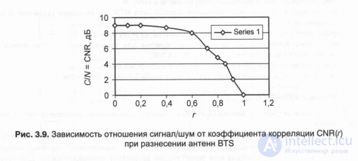
As follows from the graph of fig. 3.9, the maximum value of CNR = 9.5 dB with a correlation radius r = 0, and with a correlation radius r = 0.6 - CNR = 8 dB.
Thus, when designing the spaced antennas, it is advisable to obtain a correlation coefficient r = 0.6, with CNR-8 dB.
To provide these values of the correlation coefficient r and the CNR ratio, it is necessary to choose the antenna system configuration for r = 0.6.
Consider the most frequently used antenna system in the form of spatially separated antennas in the horizontal plane. In fig. Figure 3.10 shows the dependence of the correlation coefficient r (d / X) on the antenna interval d / X at two values of the BTS antenna heights: hi = 120 m and hi = 45 m, subject to the Gaussian distribution of the received signals.
From the graphs of fig. 3.10 follows:
- with increasing height of the antennas hi, the value of g increases with d / X = const (for example, with d / X = 5, hi = 45 m - g = 0.4, with d / X = 5, hi = 120 m - g = 0.6);
- with the standard deviation sh = 1, the dependence of g (d / X) is such that if r = 0.6, then d / X ~ 7, that is, for GSM 900, the distance between the separated antennas will be d = 2.31 m;
- it should be noted that the d / X spacing at r ~ 0.6 depends on the terrain conditions: city, suburb, forest, etc.
Experiments show that with CNR ^ YudB and r = 0.5, the magnitude of the antenna interval is d / X ^ 10.
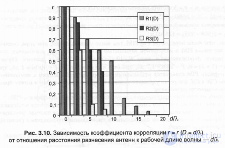
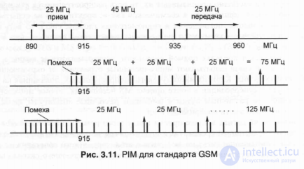
Fig. 3.11. PIM for GSM standard
For the case m = n = 3, the frequency of intermodulation waves will be:
// ms = 3 / - 3fj = 3 (960 - 935) = 75 MHz,
For the case t = n = 5, the frequency of intermodulation waves will be: frns = 5 (960 - 935) = 125 MHz.
So, the higher the order (m + n) PIM, the higher the level of interference, while the evaluation of the relationship between the PIM order and the radiated power of the antenna system shows that the interference power is defined as P ~ 10 dB / (ha + n), that is, in this case: with (ha + n) = (3 + 3) = 6, P ~ 10/6 = 1.7 dB, with (t + n) = (5 + 5) = 10, P = 10 / 10 = 1 dB, the third and fifth orders of the PIM become interfering factors leading to a change in the C / N and C // ratio, which drastically worsens the conditions for receiving signals from MS and can lead to a drop in radio communication power.
Therefore, in practice, the following measures suppress the effect of PIM:
- for antenna radiators instead of a wired element a printed circuit board is used;
- for connections between the radiator and the flange, dense fixation of silver-plated materials with special conductive gaskets is used (welding is possible);
- a ban is imposed on the use of aluminum or nickel in contacts at the joints;
- oxides, rust, etc. are detected and eliminated.

Comments
To leave a comment
GSM Basics
Terms: GSM Basics