Lecture
As discussed above, in a cellular mobile communication network, each cell is serviced by its transmitter of a BTS base station with a small output power (P £ 50 W) and a limited number of communication channels. Theoretically, such transmitters could be used in neighboring cells if, in practice, the cells were not covered by various factors, for example, due to changes in radio propagation conditions. That is, the same frequencies (channels) could be reused in different cells if the effect of mutual interference between mobile subscribers would be insignificant.
However, in practice, the mutual influence of mobile stations of MS subscribers having the same operating frequencies must be taken into account. Therefore, the concept of frequency reuse has been developed, that is, in each cell shown in Fig. 2.2, a specific group of t-channel radio frequencies is used.
So, frequency reuse (frequencyreuse) lies in the fact that neighboring cells use different frequency bands Ft, which are repeated over several hundred. To understand the essence of the principle of frequency reuse, let’s look at a few examples of building cellular network models.
1. Let in some cell A (Fig. 2.4) some part of the full frequency range allocated to the cellular mobile communication system is used (for example, for definiteness, one-tenth of the range is 6 ^ = 1/10). Then in the adjacent cell B, the second tenth part of the band b = 1/10 should be used, since the same frequency channels cannot be used near the common border in two adjacent cells. In cell C having common borders with cells A and B, it is necessary to use the third tenth of the range (6C = 1/10). But already in cell D having common borders with cells A and C, but not having common borders with cell B, the same tenth part of the range LB = 1/10 can be used again as in cell B, which is conventionally denoted D B. Similarly, in cells: £ A, FB, I C, that is, we obtain a cellular structure consisting of 3 frequency (3 element) groups, called clusters, that is, a group of cells with a different set of operating frequencies.
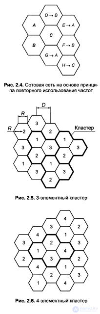 2. In fig. 2.5 shows a cellular network with a 3-element cluster: Fu F2, F3.
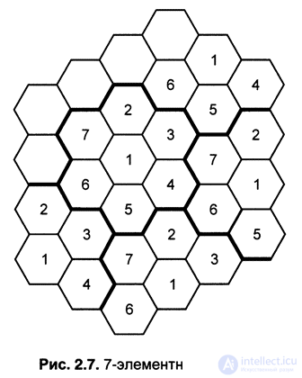
So, in cellular networks, the principle of frequency reuse in non-adjacent cells is applied, and the cluster sizes can reach values up to 19.
3. In fig. 2.6 shows a cellular network with a 4-element cluster, and Fig. 2.7 - with a 7-element cluster.
Obviously, a 3-element cluster is a cluster of the smallest possible size; in each of its cells, 1/3 of the full range of operating frequencies allocated to a cellular communication system can be used. With a 3-cell cluster, cells with the same frequency bands repeat very often, which is bad in terms of co-channelinterference, that is, interference from radio stations of the cellular system operating on the same frequency radio channels, but in different cells. In this respect, clusters with a large number of elements are more favorable (Fig. 2.6, 2.7).
In the general case, the distance D between the centers of the cells (Fig. 2.5), in which the same frequency groups (frequency bands) are used, is related to the number Nс per cluster in the simple relation:
D = R (3N) w, (2.1) where R is the radius of the cell (the radius of the circle described around a regular hexagon). For example, when the number of cells in a cluster is equal to N = 3, the value is D = 3R; for N = 4 - D = 3.46 / ?; when N = 7, D = 4.58 R; with N = 8, D = 4.9 R; with N = 12, D = 6R; with N = 19, D = 7.55R.
The value of the ratio D / R = q is often called the coefficient of co-channel interference reduction or co-channel repetition coefficient.
For 1 / N = С, the reciprocal of the number of cells in a cluster, the name is used: frequency reuse efficiency factor or simply frequency reuse factor. The introduction of these values allows to write the expression (2.1) in the form:
D = R- (b / C) m. (2.2)
It should be noted that the increase in the number of elements in a cluster, which is advantageous from the point of view of reducing the level of co-channel interference, leads to a proportional decrease in the frequency band that can be used in a single cell.
 Therefore, practically the number of elements in a cluster should be chosen as low as possible, ensuring an acceptable signal-to-noise ratio.
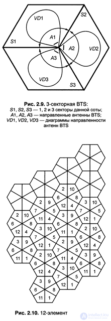
All of the above in this section, however, is nothing more than a diagram explaining the idea of the principle of frequency reuse, but not reflecting all the complexities of processes in real cellular networks. In these circuit examples (Fig. 2.5, 2.6, 2.7) it was suggested that at the BTS base stations located in the centers of ideal cells, omnidirectional antennas [or omni], that is, the emission of radio signals from the base stations, are used. 2.7. The 7-element cluster had to occur with the same power in all directions, which for subscriber MS is equivalent to receiving interference from all base stations from all directions. Therefore, to reduce the level of interference in modern digital cellular mobile communication systems, base antennas, such as sector antennas, are used in BTS base stations.
4. In fig. 2.8 shows a cellular network with a 9-element cluster, which is widely used in digital standards for cellular mobile networks.

In this 9-cluster model, the cells are divided into sectors. In the center of the cell at the base station BTS installed three directional antennas, each of which covers a sector of 120 °. In each sector of the cell, the radio signal from the corresponding directional antenna
emitted only in one direction. At the same time, the level of radiation in opposite directions, and therefore in two sectors of a given cell, is maximally reduced (Fig. 2.9).
 This circumstance allows the BTS base stations operating at the same frequencies to be located even closer to each other than in the model of Fig. 2.7. In fig. 2.8 9-element cluster gives the value of D = 5,196R when the value of C = 1 / N - 0.11.
5. Motorola (USA) has developed an even more efficient frequency reuse model. In fig. 2.10 shows a cellular network developed by them with 12 groups of carrier frequencies, using 602 directional antennas (that is, 6 directional antennas are installed at the BTS base station, the main lobe of radiation patterns of which radiates only within its 60 ° sector).
This cellular network allows you to increase subscriber capacity, that is, the number of subscribers that can be served by a cellular mobile network, 1.5 times compared with the model in Fig. 2.8.
As noted in [2.13], the GSM standard often uses 7-element clusters to create a cellular mobile communications network.

Comments
To leave a comment
GSM Basics
Terms: GSM Basics