The following types of power control systems are used in cellular mobile communication systems.
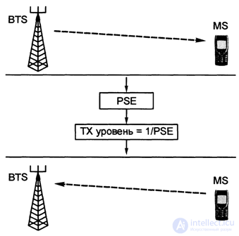
open circuit power control should be based on an estimate of the state of the radio channel.
In the reverse radio link, the state of the radio channel is estimated by measuring the power level of the received pilot signal from the BTS base station in a straight line (from BTS to MS) and setting the transmitted power level inversely proportional to TX level = 1 / PSE, i.e. IX level (transmitter power ) is inversely proportional to PSE (Pilot Strength Estimation) - an estimate of the level of the pilot signal. Using an estimate of the magnitude of the transmit power to be installed, the base station BTS provides the average level of received MS power, while the level of power radiated by the BTS should be constant, independent of variations in the channel state.
In this approximation, it is assumed that the signal levels in the forward and reverse lines are highly correlated.
The forward and reverse lines are divided by carrier frequencies (that is, different operating frequencies are used for the forward and reverse radio links), therefore fading will have a different level, and long-term channel fluctuations arising due to shading and losses during radio wave propagation have basically the same order
- received signal level;
- signal-to-noise ratio in the received signal;
- error rate in bits BER (Bit Error Rate) of the received signal;
- frame error rate (FER) of the received signal, or a combination of the listed metric elements.
In the case of reverse power control of a radio link, this metric can be directed towards the MS, as a base, for solving autonomous power control, or the metric can be estimated at the BTS and transmitted via radio to the MS as an MS power control command.
In fig. Figure 4.24 shows the order of command movement in BTS and MS for controlling the power of a reverse (reverse) closed circuit communication line - RLCLPC (Reverse Link Closed Loop Power Control).
The following operations occur under the influence of a signal from MS in BTS:
- metric score - ME (Metric Estimation);
- comparison with the reference metric - Compare with Reference Metric;
- relation to other users —Relate to Other Users;
- command to control the output power - ISSUC РСС (Power Control Command).
Further, the controlled output power creates in the cell space an electromagnetic field, which is received by the MS antennas and then to the MS, where they are performed:
- command to control the received power - RPCC (Receive Power Control Command);
- a decrease in the power transmitted from MS by a certain number of times - In / Decrement Transmitted Power.
Thus, in the scheme of fig. 4.24, the power management process is implemented: MS-BTS - MS - BTS ... etc.
It should be noted that the decision to control the power in the reverse radio link is made on the basis of decision making in the BTS.
The solution may also be based on a summary knowledge of individual MS characteristics or a group of MS characteristics, such as for MS in a sector, cell, or in any cluster of a cellular network.
If the power management solution for individual MSs is implemented in the BTS or in the switching service for all MSs and is based on knowledge of the characteristics of all other MSs, then a central power control system is formed, but more difficult to implement, more expensive and with higher process requirements. .
3 Direct Link Closed Loop Power Control - Forward Link Closed Loop Power Control.
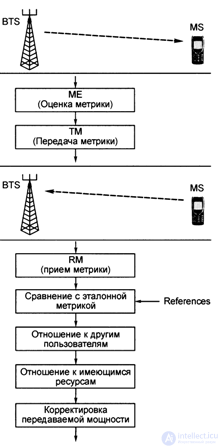
In fig. Figure 4.25 shows the implementation of power control in a closed-circuit radio link: BTS - MS - BTS - MS ..., etc., with the pilot signal moving from BTS to MS and then the following sequence is implemented in MS:
- metric score - ME (Metric Estimation);
- transmission metrics - TM (Transmit Metric).
In turn, BTS implements:
- receive metrics - RM (Receive Metric);
- comparison with the reference metric;
- relation to other users;
- relation to available funds (resources);
- installation (adjustment) of the transmitted power.
In the ideal case, power management compensates for losses during propagation, shadowing and fast fading.
There are numerous factors that influence power management and impede the realization of the ideal case.
These include:
- fast fading speed;
- limited latency for power control systems;
- non-ideal estimates of the radio channel;
- errors in the transmission of power control commands;
- limited dynamic range, etc.
They all contribute to the degradation of power control system performance.
GSM power management features
Adjustment (control) of power in the GSM standard includes the following features:
- in MS mobile stations, only the minimum power level required to ensure reliable communication with the BTS is used;
- GSM has 8 classes of BTS and 5 classes of MS in terms of the output power of the transmitters listed in Table. 4.5.
BTS transmitter power is adjusted discretely in 2dB steps. Power control of the transmitter reduces inter-cell interference and, thus, leads to an increase in the frequency repetition factor and system capacity.
The power of the BTS transmitters can be reduced to a minimum of -13 dBm (Pt ~ 20 mW).
 The channel capacity of any cellular mobile communication system depends mainly on the co-channel interference, the level of which can be commensurate with the level of the useful signal. Therefore, in cellular systems, various methods of reducing the level of co-channel interference are used, the main ones of which are:
 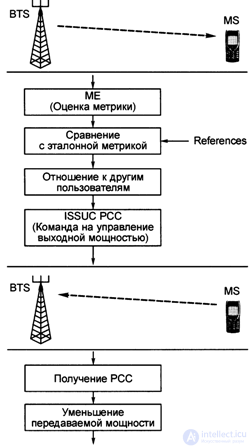 The CLPCS system is based on the metric of a valid radio link, that is, on the definition of the following parameters:

Comments
To leave a comment
GSM Basics
Terms: GSM Basics