Lecture
The channel coder follows the speech coder (Fig. 4.2) and precedes the modulator.
Its main task is noise-resistant speech coding, that is, such coding that allows detecting and substantially correcting errors that occur when propagating signals over the air from the transmitter to the receiver, for example, from the MS transmitter to the BTS receiver and vice versa.
>> Current prices on signal amplifiers - GSM repeaters
Noise-resistant coding is carried out by introducing a sufficiently large amount of redundant information into the transmitted signal, and FEC coding (Forward Error Correcting coding) can be implemented.
In cellular communication systems, robust coding is performed in the form of three procedures [4.4]:
- block coding;
- convolutional coding (convolutional coding);
- interleaving.
In addition, the channel encoder performs several other functions:
- adds control information, which, in turn, is subjected to robust coding;
- packs the information prepared for transmission and compresses it in time;
- encrypts the transmitted information.
The sequence of these functions is shown in Fig. 4.5
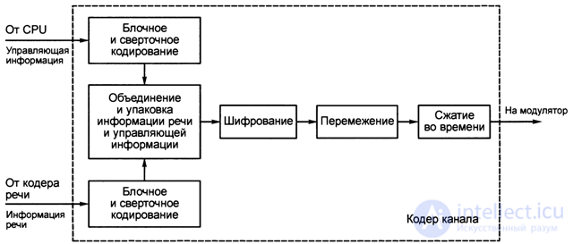
Fig. 4.5. The sequence of functions performed in the channel coder
Before the encoder and decoder of the GSM channel are considered, we will get acquainted with the basic principles of block and convolutional coding, interleaving, as well as information encryption.
Block coding
During block coding, the input information is divided into blocks, each containing k characters, which according to a certain law are converted by the encoder into “-character blocks, and n> k is selected.
The ratio of coding symbols R = k / n is called the coding rate - coding rate. The value of R <1 is a measure of redundancy introduced by the encoder.
With a rationally constructed encoder, a lower coding rate, that is, greater redundancy, corresponds to a higher noise immunity.
Increased noise immunity also contributes to increasing the length of the block at the output of the encoder. Usually a block encoder with parameters k, n is denoted by (n, k), where the first character n means the number of characters in the output block of the encoder, and k the number of characters in the input block.
Cellular systems use binary symbols of the input and output sequences.
Coders that “work” with such sequences are called binary block coders. As an example in fig. Figure 4.6 shows the binary block encoder scheme.
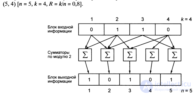
Fig. 4.6. Binary Block Encoder (5, 4)
Each bit of the output information block (at the output of adders modulo 2) is obtained as a sum modulo 2 several bits (from one to k) of the input block, for which n modulators adders 2 are used, the algorithm of which is shown in Table. 4.3.
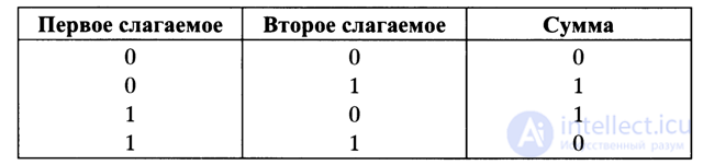
Table 4.3. The algorithm of the block encoder (5, 4)
It should be noted that one of the adders (second from the right) is degenerate, since only one term is received at its input.
In fig. 4.7 shows a systematic block encoder scheme [4.4].
As can be seen from the comparison of fig. 4.6 and 4.7, a distinctive feature of a systematic coder is that the input information block is included in the output information block. Trivial adders corresponding to the formation of this part of the output block are not shown. The simplest systematic binary block encoder (Fig. 4.8) implements the encoding operation, which consists in that the output, except for a copy of the input one, receives only one redundant bit, which is the sum modulo 2 of all the bits of the input block.
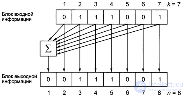
Fig. 4.7. Systematic block coder

Fig. 4.8. Byte parity check
This redundant bit is called the parity check code, since the number of characters in the output block, taking into account the check bit, is even n = 8. For an 8-bit binary information block, the diagram in fig. 4.7 may be referred to as a byte parity scheme. Using the scheme of fig. 4.7, consider the possibility of detecting errors using a block code, and then the possibility of error correction.
Byte error detection
In fig. 4.8 shows seven blocks of the output information of the encoder Fig. 4.7, with the last bit in each byte block being the parity code (that is, the input information matrix is 7x7, with 8 columns being composed of parity bits). If there is a single error in any of the 7 blocks, including an error in the parity code (8 column), the parity code generation rule is violated, on the basis of which the error is detected (for example, in line 4, if 8 appears in 1 column, then this indicates that in line 4 one of the characters is erroneous, but which one - the matrix in Fig. 4.8 does not give an answer to this).
So, the error is localized only to within a byte, and therefore can not be corrected, because it is not known which bit in the byte is wrong. Especially, if the error appeared among 7 characters of a byte and in 8 characters. Thus, the parity check in the rows does not allow to find the error of a specific bit in the matrix, but allows detecting single errors in bytes.
Byte detection and correction of block encoder errors
Consider rice. 4.9, which, in addition to the parity check in rows for all the information given in fig. 4.8 another parity check is introduced by columns (bottom 8th row)
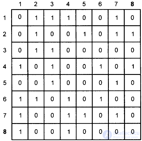
Fig. 4.9. Single byte detection and correction of a single error in a block encoder
If there is a single error in this 8x8 = 64-bit matrix, you can specify not only the line containing the error, but also the column with the error, which means the error bit lying on the intersection of the line and column (for example, if an error was detected in line 4 (1 in the 8th column), 8-byte sequence, as well as in the 4th column (1 in the 8th row), then an error bit was detected in the 4th row of the 4th column of the matrix).
So, if an erroneous bit is detected, then it can be simply corrected: if in this example - 4 line - 4 columns - error - 0, then 1 is put in place of it (or vice versa).
Thus, the matrix of Fig. 4.9 allows, when implemented in the form of systematic byte coders [Fig. 4.9 - (n, k) = (64, 49)] detect and correct single errors. However, multiple errors with this scheme cannot be fixed. For the correction of multiple errors, more sophisticated and complex schemes of block coders are used.
Convolutional coding
In fig. 4.10 shows the scheme of the convolutional encoder (4, 2, 5), where n = 4, k = 2, K = 5, R = k / n = 0.5.
During convolutional coding, the value of k consecutive characters (in this scheme K = 5) of the input information sequence with k = 2 bits in each symbol participates in the formation of n-bit (n = 4) characters of the output sequence with n> k, with each input character sequences accounted for one character output sequence.
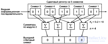
Fig. 4.10. Scheme convolutional encoder (4, 2, 5)
Each bit of the output sequence is obtained as a result of summation modulo 2 (from two to Qc bits, that is, from 2 to 5x2 = 10 bits) K (K = 5) input symbols, for which n (n = 4) modulo 2 adders are used .
So, for this scheme fig. 4.10 is a convolutional type encoder (n, k, K), where the encoder parameters: n is the number of modulo 2 adders, the number of bits of the output sequence: n = 4; K - the number of bits in each character of the input information sequence: k = 2; K is the number of characters of the input information sequence or the length of the restriction
The parameter K determines the length of the shift register (in characters), the contents of which participates in the formation of one output character (shift register 5 characters), the encoder type is written (4, 2, 5) = (n, k, K), at a coding rate R = k / n = 2/4 = 0.5. It should be noted that after the next output symbol is formed (for example, in Fig. 4.10, the first p-4 bit symbol is formed), the input sequence from the state K (0, 1) = 5, K (0, 0) = 4, K (1, 0) = 3, K (1, 1) = 2, K (0, 1) = 1 moves one character to the right, that is, instead of K = 5, we have K (0, 1) = 4, instead of K = 4 we have K (0, 0) = 3, instead of K = 3 we have K (1, 0) = 2, instead of K-2 we have K (1, 1) = 1 and as a result the symbol K (0, 1) = 1 out of register.
Symbols 2 ... 5 then move to the right, each in place of the next one, as a result of which, at each step of the character offset of the input information sequence, a new output and-bit symbol is formed, that is, in this case, the 10-bit input information sequence is “minimized” to 4 -bit output sequence, and out of 5 input symbols (2 bits each), one output n = 4-bit character is formed.
If the number of bits in the shift register characters of the input information sequence is k-1, that is, one-bit characters (and not two-bit characters, as in Fig. 4.10), then such a convolutional encoder is called binary.
In fig. 4.11 is shown as an example of a possible binary convolutional encoder scheme (4.1, 5).
Concluding the consideration of the basic principles of convolutional coding, it should be noted that the name of the convolutional code is due to the fact that it can be considered as a convolution of the impulse response of the encoder and the input information sequence.
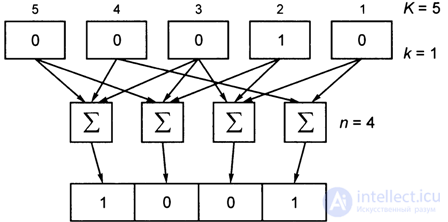
Fig. 4.11. Binary convolutional encoder scheme (4, 1, 5)
Interleaving
Interleaving is such a change in the order of the characters of an information sequence, that is, such a permutation of characters, in which the characters standing next to each other are separated by several other characters. Interleaving, as a permutation procedure, is undertaken to convert group errors (error bursts) into single errors, which are easier to deal with using block and convolutional coding.
The use of interleaving is one of the characteristic features of cellular mobile communication systems, and this is a consequence of the inevitable deep fading of radio signals in conditions of multipath propagation of radio waves, which are almost always the case, especially in conditions of dense urban development, forests, etc.
At the same time, the group of successive symbols that fall into the interval of deep signal fading with a high probability turns out to be erroneous.
If, before transmitting the information sequence to the radio channel, it is subjected to the interleaving procedure, and the previous sequence of characters is restored at the receiving end, then error packets are likely to be scattered into single errors.
There are several alternation schemes and their modifications [4.4]: diagonal; block; convolutional and other.
Let us briefly consider the diagonal and block interleaving schemes that underlie the schemes used in cellular mobile communication systems.
It should be noted that the GSM standard uses a complex block diagonal interleaving scheme.
Diagonal Interleaving
In the diagonal interleaving scheme, the input information is divided into blocks, and the blocks into subunits, while in the output sequence the subunits, for example, the second half of the previous block, alternate with the subblocks of the first half of the next block.
In fig. 4.12 a diagonal interleaving scheme is shown, where each block consists of 6 subunits A /, the second from subblocks b, and the third from subunits C /.
Each subunit can consist either of several characters, or of one character and even of one bit. As can be seen from fig. 4.12, the output sequence of subblocks bt of block 2 is interleaved with the second part of block 3 and the second part of block 1.
The diagonal interleaving scheme introduced introduces a small delay, but places the adjacent characters only through one, that is, the dispersion of the erroneous characters of the group is relatively small.
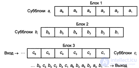
Fig. 4.12. Diagonal Interleave Pattern
Block interleaving scheme
In fig. Figure 4.13 shows the block interleaving scheme.
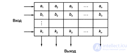
Fig. 4.13. Block interleaving scheme
During block interleaving, the input information is also divided into blocks, by l-subblocks (or symbols) in each block, in the output sequence subblocks of successive blocks alternate.
The work of this scheme can be represented as:
- records of blocks of the input sequence - as rows of the matrix of the khp dimension
- reading information that is produced in columns.
Thus, if the input sequence in this example is:
Subblocks, or characters, in the particular case, may also consist of one bit.
The block interleaving scheme introduces a greater delay than the diagonal interleaving scheme, but it spreads the error group symbols much more strongly.
A common disadvantage of both the considered schemes is the hard periodicity of following the permuted symbols within the interleaving interval.
GSM channel codec
In the channel codec, both voice information and control channel information, i.e., TCH traffic channel information and CCH control channel information, are encoded / decoded.
While only a fraction of the bits are encoded in the traffic channel information, the control channel information is encoded in full volume.
Consider the coding of the segment of the speech signal (see table. 4.1), obtained at the output of the speech coder and having:
- STP filter parameter is 36 bits,
- LTP filter parameter - 36 bits,
- parameter of the excitation signal (CB) - 188 bits,
that is, in 20 ms, 260 bits are transmitted in the speech signal segment.
In the channel coder, 260 bits of information are divided into 2 classes (Fig. 4.14):
- class 1 - it includes 182 bits protected by error-correcting coding;
- class 2 - it includes the remaining 260 - 182 = 78 bits, which are transmitted without error-correcting coding.
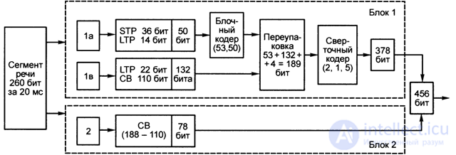
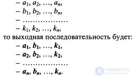
Fig. 4.14. The coding segment of the speech signal
In turn, class 1 is divided into:
- a subclass 1a to which STP short-term prediction filter parameters (36 bits) and a part of information (14 bits) about LTP long-term prediction filter parameters belong, that is, 50a (36 + 14) bits of essential speech information are allocated in subclass 1a, which is subjected to the most powerful interference-free coding;
- subclass 1c, in which the remaining 182-50 = 132 bits are included, is encoded weaker than information of subclass 1a. In subclass 1c, 22 bits of information about the parameters of the LTP filter and 110 bits about the parameters of the excitation signal are included.
Thus, the distribution of digital information (bits) in subclasses 1a, 1c and class 2 is implemented (Fig. 4.14) for a speech segment in the form: 1a - 50 bits; 1c - 132 bits; 2 - 78 bits.
Coding information subclass 1a
1. Information 50 bits is encoded by a block code - a shortened systematic cyclic code (n, k) = (53, 50), that is, a 3-bit parity code allows you to detect errors. At the output of the block coder, thus, the digital sequence has 53 bits (3 bits excess).
2. In a special block, information of subclasses 1a (53 bits) and 1c (132 bits) is repackaged, arranged in the following sequence:
- bits with even indices;
- parity code of subclass 1a;
- bits with odd indices in reverse order;
- four additional zero bits, that is only 53 + 132 + 4 = 189 bits.
3. A digital sequence of 189 bits is fed to the input of a convolutional encoder (convolution encoder) (l, k, K) = (2, 1, 5), having a coding rate R = k! N = 0.5 and the length of the K-5 limit As a result of convolutional coding, a digital sequence of 189x2 = 378 bits is obtained at the output of the encoder.
The final digital sequences of a speech segment in block 1 - 378 bits and block 2 - 78 bits together make 456 bits, that is, the speed of the speech information flow at the output of the channel encoder is 456 / 20-10_3 = 22.8 kbit / s.
However, the process of encoding speech before applying digital signals to the modulator does not end there.
The GSM standard uses a rather complicated and perfect block diagonal interleaving scheme (Fig. 4.15).
The resulting 456 bits of information of one 20-mil liter-second segment of speech are divided into 8 sub-segments, 57 bits each (456/8 = 57)
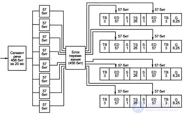
Fig. 4.15. Diagonal block interleaving scheme
Then, in the interleaver, an interleaving algorithm is implemented that has the properties of quasi-randomness, so that the adjacent bits of the original sequence are divided by a non-constant number of bits, and after interleaving 57 bits of one sub-segment are distributed between eight adjacent sub-segments in such a way that the corresponding bits of each sub-segment , spaced from it before the permutation by 4 subsegments, and even and odd (after permutation) the bit positions of the subsegment are put and adjacent segments.
As shown in [4.8], the interleaver table for a speech bit sequence is:

После перемежения (рис. 4.15) 456 бит информации одного речевого сегмента распределяются по одноименным слотам (временным интервалам) четырех последовательных кадров канала трафика: два поля по 57 бит в слоте и каждое 57-битовое поле снабжается дополнительным скрытым флажком S, помечающим информацию речи (в отличие от информации управления канала, например, быстрого совмещенного канала управления FACCH, информация которого кодируется иначе).
Итак, длина слота канала трафика, с учетом добавления вспомогательной и служебной информации, составляет 3 + 57+1 + 26 + 1+ 57 + 3 + 8,25 = 156,25 бит, и поскольку информация одного 20-миллисекундного сегмента речи занимает по одному слоту в четырех последующих кадрах, скорость результирующего потока цифровой информации составляет (4х156,25)/20х1СГ3 = 625/20х10“3 = 31,25 кбит/с.
Эта информация (а именно 4x156,25 = 625 бит) сжимается во времени в 8 раз, так что на протяжении одного кадра длительностью 4,615 мс передается информация восьми временных слотов, в результате чего частота битовой последовательности возрастает до (8x31,25) = 250 кбит/с.
На каждые 12 кадров канала трафика, несущих речевую информацию (в мультикадре канала трафика информационными речевыми кадрами являются 1-12 и 14-25, в 13* кадре передается канал управления SACCH, а кадр 26* — пустой, для резервирования) добавляется по одному кадру с информацией управления канала SACCH (имеющую скорость 20,833 кбит/с). Таким образом, скорость информационной битовой последовательности (по речевому сигналу) на выходе кодера канала составляет: 250 + 20,833 = 270,833 кбит/с.
Следует отметить, что выше была рассмотрена процедура работы кодера канала только по помехоустойчивому кодированию речевой информации.
Информация же каналов управления подвергается блочному и сверточному кодированию в полном обьеме.
Так, для кодирования информации каналов: медленного совмещенного канала управления SACCH; быстрого совмещенного канала управления FACCH; канала вызова РСН; канала разрешения доступа AGCH; выделенных закрепленных каналов управления SDCCH используются блочный кодер (п, к) = (224, 184), сверточный кодер (п, к, К) = (2, 1, 5), а также схема перемежения, аналогичная схеме перемежения по речевому каналу.
В каналах синхронизации SCH и случайного доступа RACH используются другие схемы блочного кодирования, а также сверточные кодеры (2, 1, 5), отличающиеся от сверточных кодеров перечисленных выше каналов управления.
При передаче компьютерных данных используются более сложные схемы сверточного кодирования и перемежения, обеспечивающие соответственно и более высокое качество передачи информации.
В заключение рассмотрения кодера канала стандарта GSM в табл. 4.4 [4.4] приведены основные характеристики систем кодирования речи стандартов GSM и D-AMPS (США). Последняя строка таблицы показывает эффективность использования полосы частот, которая характеризуется скоростью передачи информации на выходе кодера канала, приходящейся на
1 Гц полосы, занимаемой частотным каналом 270,833* 103/(200*103) = 1,354 (бит/с)/Гц).
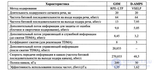
Table 4.4. Характеристики систем кодирования речи в стандартах GSM и D-AMPS
Декодер канала
Процесс декодирования информации после демодуляции выполняется в порядке, обратном кодированию (см. рис. 4.5):
1) снимается сжатие информации во времени, то есть информация возрастает во времени в 8 раз;
2) снимается перемежение, то есть восстанавливается последовательность битов после шифрования информации;
3) реализуется дешифрование информации;
4) реализуется разделение информационных потоков речи и управляющей информации;
5) при декодировании информации речи процесс идет следующими этапами:
- в начале (после эквалайзера) выполняется сверточное декодирование информации (класса 1), при этом исправляются ошибки в пределах возможностей кода свертки;
- далее по коду четности проверяется наличие остаточных ошибок в информации подкласса 1а, и, если такие ошибки обнаруживаются, информация данного сегмента не идет в последующую обработку, а заменяется интерполированной информацией смежных сегментов;
6) реализуется блочное декодирование речевой информации;
7) реализуется сверточное и блочное декодирование управляющей информации, которая далее поступает в CPU. После сверточного и блочного декодирования речевой информации сигналы (цифровая последовательность) подаются на вход декодера речи.

Comments
To leave a comment
GSM Basics
Terms: GSM Basics