Lecture
The use of sophisticated coding algorithms for relatively narrow-band speech signals (300 ... 3400 Hz) and wide-band facsimile audio signals (from 10 Hz to 20 kHz) in various radio communication systems, and image signals (up to 15 MHz) is becoming more efficient and economical from the point of view costs [4.1].
The emergence of low-power ultra-high-speed integrated circuits (VLSI) led to the use of coding algorithms in mobile telephones and the movement towards digital broadcasting. The purpose of most of these algorithms is analog-to-digital conversion of an analog signal of a source into a digital signal with the least possible number of bits and its processing, for transmission in the form of digital data and / or storing, or synthesis and recovery of noise and noise, limited by bandwidth or distorted signal. In this case, compression (compression) of digital data can be achieved by eliminating the redundancy of a signal converted from analog to digital form.
The speech coder is the first element of the digital section of the transmitting path, following the ADC (Fig. 4.2).
The main task of the encoder is the maximum possible compression of the speech signal represented in digital form, that is, the maximum possible elimination of the redundancy of the speech signal while maintaining an acceptable quality of the transmitted speech.
A compromise between the degree of compression and quality preservation is usually found experimentally, and the problem of obtaining a high degree of compression without an excessive reduction in quality is the main difficulty in the development of an encoder.
A receiver (decoder) of the speech signal is placed in the receiver (Fig. 4.2) in front of the DAC. The task of the decoder is to restore the digital signal of speech, with its inherent natural redundancy, according to the received coded signal.
The combination of the encoder and decoder is usually called a codec (coder / decoder = codec).
Voice Codec.
In the GSM standard, speech signal processing is carried out within the framework of the accepted system of discontinuous voice transmission DTX (DiscontinuousTransmission), which ensures that the transmitter is turned on only when the user starts a conversation and disconnects it during pauses and at the end of the conversation.
The DTX system is controlled by the VAD (Voice Activity Detection) speech activity detector, which provides detection and selection of speech intervals with noise and noise without speech, even in those cases where the noise level is commensurate with the speech level.
The DTX system includes a device for generating comfortable noise, which is turned on and heard in the pauses of speech (when the transmitter is turned off).
The intermittent speech transmission system also includes a device for extrapolating speech fragments lost due to channel errors.
The block diagram of the speech signal processing process is shown in fig. 4.3.
The main device in this scheme is the speech codec.
In accordance with the GSM standard, each radio channel is used to organize eight digital channels with TDMA. So, if these are standard PCM channels, then a transfer rate of 8x64 = 512 kbps will be required. This rate of transmission of user information on one radio channel is impossible to ensure.
A way out of this situation can be found, on the one hand, in increasing the density of transmitted information, and on the other, in using more sophisticated methods of encoding speech signals that require less information. Reducing the required digital bit rate of each channel through the use of more sophisticated coding methods should be carried out without significant quality degradation. The lowest information transfer rate - (1 ... 3) kbps is required when using vocoders, however, the quality of voice transmission in this case is quite low, while decoding a "synthetic" speech signal is obtained. High quality voice transmission with a slight decrease in speed requirements can be obtained with the use of various modifications of PCM, but more complex hardware implementation. In order to have high voice quality with lower data rate requirements, GSM uses a coding method that combines vocoders and differential PCM, which is called differential encoding. The coded transform is based on the use of human speech organs. Sound vibrations emitted by the vocal cords are formed further in the “filters” formed by the throat, mouth and nose. Knowing at each moment the frequency spectrum and parameters of such "filters", you can restore the original signal. Given the inertia of the human voice organs, we can assume that for a short period of time (about 10 ... 30 ms) they do not change their state, that is, the frequencies and parameters of the “filters” remain constant. Consequently, if we take segments of a speech signal by 20 ms, the frequency of the fundamental tone and the filter parameters of the speech-forming path, then it is easy to reconstruct the original signal from them. For example, in linear prediction coding, the following information is determined and transmitted: At fixed intervals, the vocal organs of a person do not remain in a fixed position, their arousal is more complex than the transmitted character of arousal and the period of the fundamental tone. This leads to a significant deterioration in quality. Differential PCM takes into account the correlation of discrete reports of the AIM signal. In this case, not the discrete samples themselves are encoded, but the difference of the amplitudes of the incoming and previous discrete samples. Since the range of variation of the amplitudes of the difference of discrete samples is less than the range of variation of the amplitudes of the discrete samples themselves, for their coding a smaller number of bits is required. Thus, differential encoding involves dividing the speech signal into 20ms segments with their previous coding. GSM codec In the GSM standard, a voice prediction system uses a linear prediction method with excitation by a regular pulse sequence and long-term prediction, that is, the RPE-LTP method. A simplified block diagram of a GSM codec is presented in Fig. 4.4.
|
Coder
Coder presented in Fig. 4.4, consists of six main blocks B.1 ... B.6 [4.4]. Consider the sequential purpose of these blocks.
B.1 - preprocessing unit performs the following functions:
- prediction of the input digital signal sn (after ADC) using a digital filter that emphasizes high frequencies;
5- 632
- separation of the input signal sn in segments of 160 samples (20ms);
- weighting of each of the segments by the Hamming window (“cosine on the pedestal” - the signal amplitude smoothly decreases from the center of the window to the edges).
B.2 - STP filter-analyzer: from the output of block B.1, the signal is filtered by a short-term linear prediction lattice filter-analyzer and its output signal — prediction residual STPn — is estimated LTP long-term prediction parameters: prediction coefficient g and time delay d in block B.5 .
B.3 - STP filter parameter evaluation unit: for each 20 ms segment, the parameters of the STP filter analyzer — 8 partial correlation coefficients kt (i = 1 ... 8) are estimated, with the prediction order M = 8 (/ = 1 ... M ), which, for transmission over a communication channel, are transformed into logarithmic ratios of the LARrh areas. For the logarithm function, a piecewise linear approximation is used.
B.4 - LTP filter analyzer: the prediction residual signal L is filtered by the LTP filter of a long-term linear prediction, and the LTP prediction residual is formed - v „.
B.5 - LTP filter parameter evaluation unit: in the block by the STP residue — b, the long-term prediction parameters g and d are estimated. At the same time, the sample segment of the short-term prediction residue, having 160 samples, is divided into four sub-segments of 40 samples each, and g and parameters d are estimated for each subsegment separately, and to estimate the time delay d for the current subsegment, a sliding subsegment of 40 samples is used, moving within the preceding 128 samples of the prediction residual signal Ln.
B.6 - block of parameters evaluation of the excitation signal: the output signal of the LTP filter-analyzer — prediction residual vn — is filtered by a smoothing filter and the excitation parameters are generated by it, separately for each of the 40 selected sub-segments. The excitation signal of one subsegment consists of 13 pulses, following at equal intervals of time (three times larger than the sampling intervals of the signal after the ADC — that is, the original signal), and having different amplitudes. For the formation of the excitation signal, 40 pulses of the smoothed remainder subsegment v „are processed as follows:
- the last fortieth impulse is discarded;
- the first 39 pulses are divided into three sequences:
■ in the first sequence - pulses 1, 4 .. .37;
■ in the second - impulses 2, 5, ..., 38;
■ in the third one - impulses 3, 6, ..., 39.
As the excitation signal is chosen from the sequence, the energy of which is greater. The amplitudes of the pulses are normalized with respect to the pulse with the highest amplitude and the normalized amplitudes are encoded with three bits each with a linear quantization scale. The absolute value of the largest amplitude is encoded by six bits on a logarithmic scale. The position of the initial pulse of the 13-element sequence is encoded with two bits, that is, the number of the sequence selected as the excitation signal for this sub-segment is specified.
Thus, the output information of a speech encoder for a single 20 ms speech segment includes:
- parameters of the filter-analyzer STP — 8 coefficients of the logarithmic ratio of the areas LARg, (/ = 1 ... 8) - one set for the whole segment;
- LTP filter-analyzer parameters — long-term prediction coefficient g and time delay d for each of the 4 sub-segments; —parameters of the excitation signal — sequence number n, maximum amplitude B, normalized amplitudes bt (1 ... 13) of pulse sequences — for each of 4 subsegments.
The number of bits allocated for coding the transmitted parameters is given in Table. 4.1.
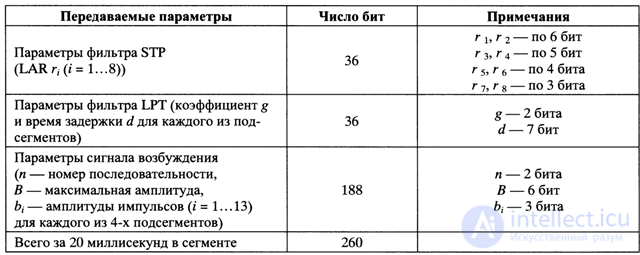
Only for one 20-ms segment of speech, 260 bits of information are transmitted, that is, the speech coder performs data compression almost 5 times (1280/260 = 4.92, where 1280 = 160x8 is the number of bits in the linear prediction method).
Decoder.
Consider the principle of decoding information received over a communication channel in accordance with the scheme of Fig. 4.4.
1. Excitation signal generation unit 1.B, using the received parameters of the excitation signal, reconstructs the 13-pulse excitation signal sequence for each of the speech signal subsegments, including the amplitudes of the pulses and their location in time, that is, the signal as the remainder of the long-term prediction is fed to the input 2.B - filter synthesizer LTP.
2. The excitation signal generated in this way is filtered by a synthesizer filter of the long-term LTP prediction, the output of which is the reconstructed residue of the short-term prediction <Y. It should be noted that signals are transmitted to the second input of the LTP filter, transmitting the long-term linear prediction parameters, namely the long-term prediction coefficient gand the time delay d.
3. The signal — the remainder of the multi-time prediction L'n — is fed to an STP trellis filter synthesizer, which implements filtering of the 6 ^ signal, and the filter parameters are pre-converted from LAR * to partial correlation coefficients kt.
4. In 4.B - filtering block, the output signal from the filter synthesizer STP is filtered in (post-filtering block) by a digital filter restoring the amplitude ratio of the frequency components of the speech signal, that is, in the coder block B.1 introduces compensating predistortion, and in block 4 .B decoder recovers digital speech signal.
Thus, after decoding, a digital speech signal S'nSn is obtained.
Evaluation of the quality of speech coding.
As follows from consideration of the functioning of the GSM codec, the creation of an economical and perfect speech codec is a complex process associated with the continuous search for new technical solutions.
When assessing the quality of codec coding, speech intelligibility and quality of synthesis (sound quality) of speech are evaluated.
To assess speech intelligibility, the DRT (DiagnosticRhymeTest) method is used - diagnostic rhymed text. In this method, pairs of words that are close in sound, differing in individual consonants (such as “house” - “volume”, “count” - “goal”), which are repeatedly pronounced by several speakers, are selected, and the proportion of distortions is estimated from the test results. The method allows to obtain an assessment of the intelligibility of individual consonants and a general assessment of speech intelligibility.
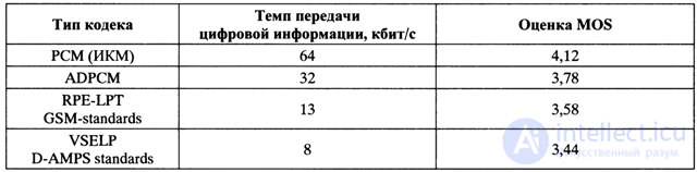
To assess the sound quality, the DAM (DiagnosticAcceptabilityMeasure) criterion is used - a diagnostic measure of acceptability. The tests consist in the reading by several speakers (men and women) of a number of specially selected phrases that are tapped at the output of the communication path by a number of experts who put their marks on a five-point scale. The result is the average subjective score or average MOS score (MeanOpinionScore). Although the method of estimating sound quality by the MOS criterion is subjective, its results are fairly objective and are used in practice.
As an example, in the table. 4.2 shows the results of the evaluation of four types of codecs according to the MOS criterion.
The results close to the MOS scale are provided by an objective method of quality assessment using the notion of cepstrum CD distance (Cepstrum Distance).
It should be noted that when developing the GSM standard, six types of codecs were investigated, after which the choice was stopped on the RPE-LTP codec.
Works on improving codecs in the GSM standard continue:
- half rate coding (6.5 kbps) was introduced,
- proposed new improvements to the full-speed codec [4.6, 4.7].
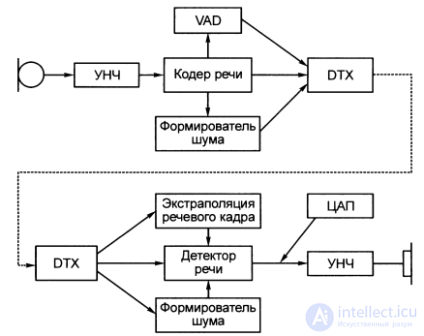 Fig. 4.3. Block diagram of the process of processing a speech signal in the GSM standard
 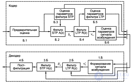 Fig. 4.4. GSM voice codec scheme
Comments
To leave a comment
GSM Basics
Terms: GSM Basics