Lecture
Since the decimeter wavelength range is used in cellular mobile communication systems, electric dipole antennas are usually used as antennas.
Understanding the characteristics and design of such antennas requires a clear understanding of the transmission and reception parameters of an elementary electric vibrator (dipole), which will make it easier for the reader to become familiar with specific antennas of base and mobile stations, as well as provide a basis for understanding the methods of calculating the electromagnetic field emitted by MS and antenna. Bts.
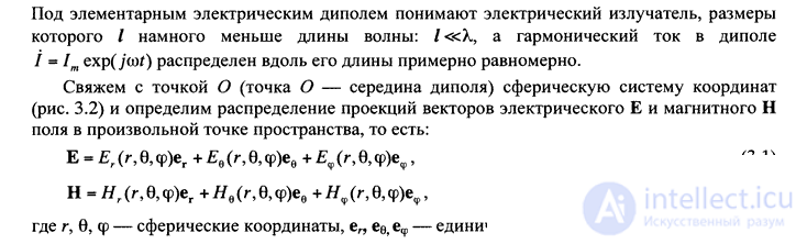
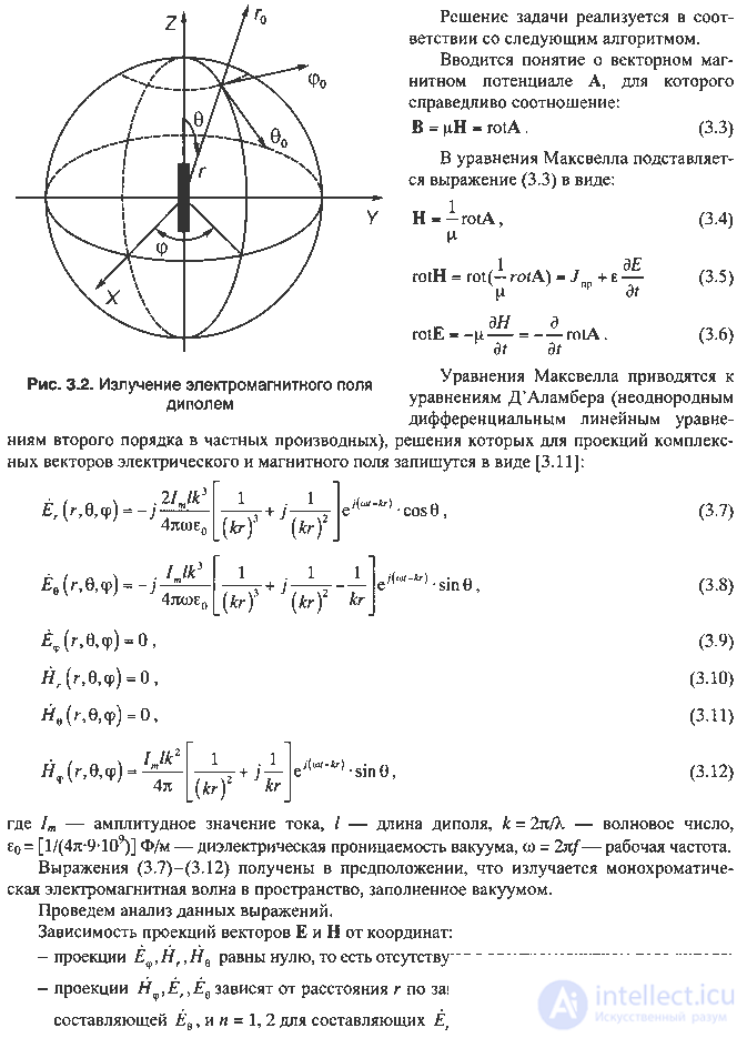
Radiation of an electromagnetic field by an elementary electric dipole.
that is, the magnetic field in the near zone relative to the electric field is shifted by 90 ° in phase.
Therefore, the power flux density (Umov-Poynting vector) is represented as:
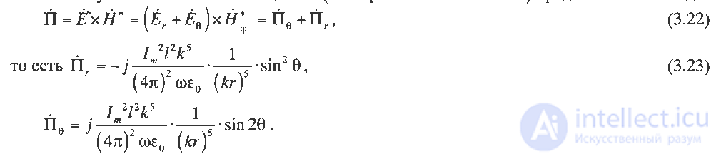
This means that in the near zone, in the ideal case, there is no radiation, since the components of the Umov-Poynting vector are purely complex.
In reality, there is a large reactive field in the near zone, and the radiation field (extending from the emitter-dipole into the surrounding space) is extremely small (since values of 1 / (kg) 2 are significantly greater than 1 / (kg)) compared to the reactive field.
Thus, a reactive electromagnetic field occurs in the near zone, and the power flux density is much greater than in the far zone — the radiation zone. The intermediate zone is transitional from the near to the far zone, when the value

that is, none of the terms 1 / (kr) n in expressions for the projections H ^, Er, E is neglected
not as it was done for the near zone. This leads to the fact that in the intermediate zone the radiation field and the reactive field are of almost the same order. The expressions for Well, Yog, Yedlya intermediate zone allow us to investigate the structure of the electromagnetic
electric dipole fields. It should be noted the following:
- in the intermediate zone, also called the Fresnel diffraction zone, the monotonous decrease of the components from the distance according to the law 1 / imposes an oscillating, decaying field of a reactive nature;
- the modules of the projections of the vectors E and H with different laws of change 1 / g in the intermediate zone are similar values;
- The electromagnetic energy radiated by a dipole is distributed in a complex manner in the space surrounding the electric dipole and depends on both time and spatial coordinates.
In addition to the radiated energy, an oscillating mode arises in the intermediate zone (the energy then "goes away", then "returns" to the dipole), which leads to an increase and decrease in the power flux density at different distances from the radiator, that is, a mode of mixed electromagnetic waves arises in space.
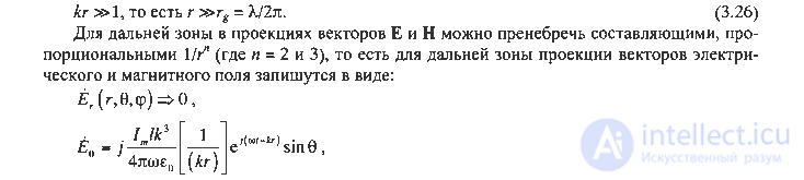
The far zone, often called the wave zone or radiation zone, is characterized by the condition:
The main parameters of the elementary electric dipole Power and radiation resistance
The propagation of electromagnetic waves (EMW) in the far zone is accompanied by the transfer of energy and the associated power flux density.
The average for the period of the power flux density vector (Umov-Poynting vector) is equal to:
Directional properties of the electric dipole.
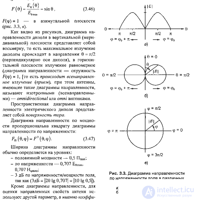
For a more visual understanding of the nature of the dipole radiation (and, in general, for the dipole antennas used in the decimeter range in MS and BTS), graphs of the amplitude of the electromagnetic field intensity (i.e. £ e (v, sr) or // F ( 0, ф)) or power flux density Пг (0, ф) from the direction to the observation point with a constant radius r = const, or in Cartesian - fig. 3.3, a, or in the polar coordinate systems.
In fig. 3.3, the dependences of the normalized values of the electric field strength emitted by the dipole on the corresponding angular coordinates, called radiation patterns in the polar coordinate system of the meridional plane (Fig. 3.3, b):
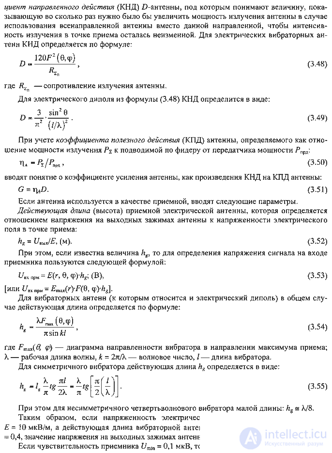
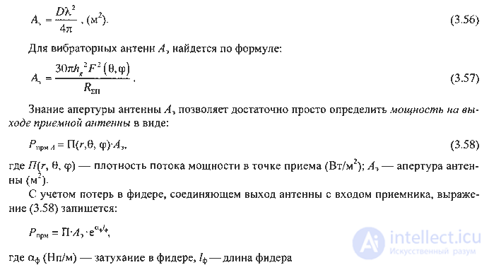
Aperture - the effective area of the antenna Ae, that is, the area from which the receiving antenna extracts the energy of the electromagnetic wave incident on it, is determined by the formula:
In conclusion, it should be noted that the foregoing will be further used both for estimating the parameters of antennas used in the equipment of cellular mobile communication systems and in studying the conditions of radio wave propagation and reception of signals by mobile and base stations.

Comments
To leave a comment
GSM Basics
Terms: GSM Basics