Lecture
Designing and building new production facilities is advisable if and only if there is reliable market research data on the stable, long-term demand for the products planned for production.
In other words, this means that the product life cycle must fully recoup all the costs associated with the design * , construction and operation of production.
The basis for creating a new production are the demand (production volumes) and the labor intensity of the products. Production practice has proven that those areas where parts have a high degree of structural and technological similarity work most effectively. There are many methods for determining the similarity of different objects among themselves. The simplest and less time consuming, in our opinion, is the method of determining similarity (a measure of proximity) using a potential function developed by de. n., Professor V. A. Petrov.
The use of a potential function in the formation of sections allows us to distinguish two stages in their design: macro-design and engineering design.
Macro-design contains four successive stages.
Stage 1. Analysis of the constructive-technological generality of the composition of products is carried out using the classification of parts for the entire range. The purpose of the classification is to obtain indivisible sets of uniform in design and technological processes for processing parts.
It should be noted that the results of PS design and its effective work in the future depend on the thoroughness of the implementation of the stage in question.
A positive result of the analysis largely depends on the choice of classification criteria.
Under the classification signs understand the set of parameters and characteristics of the objects under study, which fully reflects the distinctive properties inherent in this entire set.
The larger the set of features, the more accurate the selection of similar objects.
However, an excessive set of signs increases the complexity of the analysis and the subsequent necessary calculations.
Given the above, we note that the set of classification signs should be minimally sufficient and allow you to divide the entire set (product range) into groups that are similar in all parameters.
Under the conditions of instrument-making and mechanical engineering, the main such signs include the type of blank (P1), the overall dimensions of the parts (P2), the main operational route (P3), the structural type of the part (P4).
The first sign determines the general nature of processing and the choice of the type of equipment. As a result of classification by this criterion, the entire set of parts is divided into classes, for example, classes of parts made of forgings, castings, rolled round or strip material.
The second sign determines the overall dimensions and power required for processing equipment.
The third sign takes into account the operational technological processing of parts. On this basis, parts are distributed to workstations equipped with process equipment, in accordance with the process.
The fourth sign establishes in the final analysis the composition of groups of parts.
In addition, the design type of parts determines the choice of types and models of technological equipment.
The results of the first stage are:
Stage 2 Analysis of determining the planned organizational characteristics of the details. Among the main planning and organizational indicators should include the labor intensity of the production of parts (t) and the volume of production N.
These factors largely determine the stability of production conditions in the workplace and the nature of movement of parts in production, i.e. temporary structure of the production system.
For grouping parts according to the labor intensity of their manufacture and the volume of their production, reflecting the degree of stability of working conditions at workplaces, the indicator of relative labor intensity * of parts K gi is used . It determines the estimated total number of units of anonymous equipment needed to process the i- th part for a given production volume, technology, and work shift mode. The calculation procedure is presented in table. eight.
T a b i c a 8.
The calculation of the relative labor intensity of parts
Name of the calculated value | Formula for calculating |
| Annual effective fund of working time of the machine, h |  |
| Annual launch volume of the i-th part, pcs. | 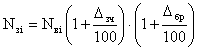 |
| Relative laboriousness indicator * Representative details |  |
| Indicator of relative labor intensity * by type of parts |  |
Legend to the table. eight:
D is the number of working days in a year (D = 261); f - the duration of the shift, hours (f = 8.2 hours); C - the number of shifts per day (two-month mode of operation); K p - the average reduction rate of the fund time for a scheduled overhaul (0.95  K p 0.98); N in - the annual volume of the planned production of the i-th part, pcs. (see information card);
  SC - the percentage of parts going to spare parts; br - the percentage of production losses from marriage * ; t pieces - piece time of processing the i-th part for the j-th operation in normal-min .; K oi - the number of operations on the main technological process of the i-th part; K in - the average rate of implementation of the norms of time (1,0 K in 1,2); m i - the number of parts (item positions) included in this type group.
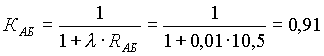
Stage 3 Calculation of a measure of proximity between two groups of parts. One of the conditions for the highly efficient operation of an enterprise is the design of its workshops and sites according to the principle of a subject, and even better in the exploded form of their specialization. The fulfillment of this condition is achieved by the method of further detailing and analyzing groups of parts that are homogeneous in structural, technological, and organizationally planned characteristics formed at the second stage. The solution * of this problem is based on the principles of pattern recognition theory using a potential function that establishes a measure of proximity between groups of parts. This function has the following form:
 ,
, where K xixj is a measure of proximity * between groups of parts (x i x j ); R xixj - a measure of the distance between x i and x j groups of parts for a number of signs;  - coefficient of proportionality of the measure of proximity.
Proportionality value selected for the entire set of details of the group, based on the following algorithm:
0.1 if R 2 = 1  9 = 0.01, if R 2 = 10 99
0.001 if r 2 = 100 999, etc.
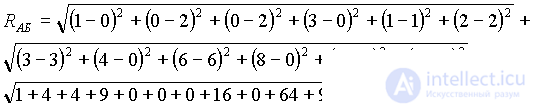
In turn, R 2 (x i x j ) is the square of the distance measure between the base representative part (x i ) and all other details (x j ), which is calculated from the code values, in the following relationship:
R 2 (xixj) = (x 1i - x 1j ) 2 + (x 2i - x 2j ) 2 + (x 31i - x 31j ) 2 + (x 32i - x 32j ) 2 +? + (X 3ri - x 3rj ) 2 + (x 4i - x 4j ) 2 + (x 5i - x 5j ) 2 ,
where: (x 1i - x 1j ); (x 2i - x 2j ); (x 4i - x 4j ); (x 5i - x 5j ) - the difference between the codes between the basic representative part x i and the representative parts x j according to feature P 1 ; P 2 ; P 3 ; P 4 ; P 5 .
The measure of the distance (Rx i x j ) between the parts included in the groups formed at the first stage is carried out through the codification system of the parameters or features of each accepted feature.
The feature code is a numerical value assigned to each parameter selected to characterize the selected features.
For example, on the basis of dimensions (P 2 ), separate groups of parts with limits of limiting dimensions can be distinguished. Dimensions  ten 50 - 1st group > 50 100 - 2nd group, etc. Or type of workpiece (P 1 ) - 1st group - from bar and rolled, - 2nd group - sheet material.
The following rules must be followed when encoding:
When calculating the distance measure in each group of parts, a representative part is selected, with which all the parts included in this group are compared.
As a rule, the most time-consuming part of the group with the largest number of technological operations of the production process is taken as the representative part.
All actions and calculation results are recorded in the form 8.1.
As an example, consider a fragment of coding and calculating a measure of proximity between the details of a formed group.
According to the analysis of the structural and technological commonality of parts, similar groups were formed - shafts, gears, bodies, etc.
Suppose that in the shaft group there is the most time-consuming detail A (representative detail) with the following parameters for the following features:
type of billet (P 1 ) - rolled steel;
overall dimensions (P 2 ) - 85 mm;
the operational technological route (P 3 ) - turning (T) - milling (Fr) - drilling (Sv) - hardening (G) - grinding (Shl) - metalworking (Sl);
constructive type (Р 4 ) - stepped shaft.
This group includes part B with parameters: P 1 - forging; P 2 - 45 mm; Р 3 - turning - milling - drilling - grinding; R 4 - simple shaft.
Applying the coding rules, the form 8.1 is filled in according to all signs with the assignment of a code (numerical value) to each parameter.
Form 8.1.
Groups | Signs of | R xixj | ||||||||||||
P 1 | P 2 | P 3 | P 4 | |||||||||||
Rental | Forging | five | 51 | T | Fr | St | H | Shl | Sl | Stup. shaft | Simple shaft | |||
Shafts | BUT | one | - | - | 3 | one | 2 | 3 | four | 6 | eight | 3 | - | one |
B | - | 2 | 2 | - | one | 2 | 3 | - | 6 | - | - | 2 | 0.91 | |
According to the values of the codes, we determine the measure of the distance between the parts A and B:
We define the measure of the proximity of parts A and B through a potential function.
Then, calculations are made of the measure of the proximity of the representative product * (A) with all the details included in this group.
The same calculations are carried out for the rest of the constructive-technological groups, highlighting in them a detail representative for comparison with other details of the group in question.
The results of the calculations serve as the basis for the next stage of work on assigning parts to shops and sites.
4 stage. Synthesis of analysis results. The task of the stage is to select parts in groups with a high degree of proximity, i.e. with the same or similar values of K xixj .
Practice has shown that a sufficient similarity of details is determined by a discrepancy in the value of K xixj of no more than 15%. Such parts are combined into separate groups and are the basis for the engineering design stage.

Comments
To leave a comment
Management
Terms: Management