Lecture
Unfortunately, in real resistors, in addition to the basic parameters for the sake of which this radio element was created, there are parasitic parameters due to the design features of the resistor. Equivalent resistor circuit with spurious parameters is shown in Figure 1.
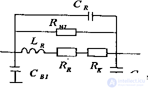
Figure 1. Equivalent resistor circuit
In this scheme, C в1 and C в2 are the capacitances of the terminals of the resistors relative to the common wire, C R is the capacitance between the terminals of the resistor, R r is the resistance of the resistive layer, R c is the contact resistance, R i is the resistance of the protective coating (usually glass), L R is the inductance of the terminals of the resistor and its resistive layer. The most harmful parameter is the parasitic inductance. A slightly smaller value is played by the parasitic capacitance of the resistor. Both of these parameters limit the maximum frequency to which a particular type of resistor can be applied.
The best frequency parameters currently have surface-mounted resistors. It is this, together with their low cost and low cost of installation, that in modern equipment resistors are used exclusively of this design. Figure 2 shows typical frequency characteristics of surface-mounted resistors.
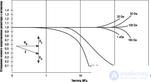
Figure 2. Typical frequency response of surface mounted resistors
The appearance of surface-mounted resistors (SMD) is shown in Figure 3.
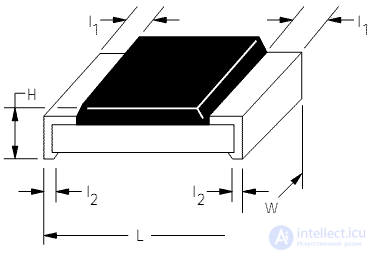

Figure 3. The appearance of the surface-mounted resistor
The appearance of surface-mounted resistors (smd) for different sizes looks the same. Table 1 shows the dimensions and maximum power dissipation of standard size resistors.
Table 1 The main dimensions of surface mounted resistors
| Resistor type | Dimensions (mm) | P (mW) 70 ° C | MAX RCWV (V) |
|---|---|---|---|
| 01005 | 0.4 × 0.2 | 31 | 15 |
| 0201 | 0.6 × 0.3 | 50 | 15 |
| 0402 | 1 × 0.5 | 63 | 25 ... 50 |
| 0603 | 1.6 × 0.8 | 63 ... 100 | 50 ... 75 |
| 0805 | 2 × 1.25 | 100 ... 125 | 125 ... 150 |
| 1206 | 3.2 × 1.6 | 125 ... 250 | 150 ... 200 |
| 1210 | 3.2 × 2.6 | 250 | 200 ... 250 |
| 1812 | 4.5 × 3.2 | 500 | 200 ... 250 |
| 2010 | 5 × 2.5 | 500 | 200 ... 250 |
| 2512 | 6.4 × 3.2 | 1000 | 200 ... 250 |
Despite the apparent simplicity, cheapness and prevalence, the modern surface-mounted resistor is a very complex device, in the manufacture of which many of the achievements of modern high-tech are used. In order to verify this, it is enough to look at the simplified diagram of the internal device of the SMD resistor, shown in Figure 4.
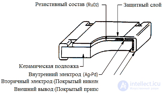
Figure 4. Device surface-mounted resistor
The main carrier element of the resistor is a substrate made of aluminum oxide (Al2O3). This material has good dielectric properties, but in addition it has a very high thermal conductivity, which is necessary for the removal of heat released in the resistive layer to the environment. The basic (but not all!) Electrical characteristics of a resistor are determined by a resistive element, which is most often used as a metal or oxide film, such as pure chromium or ruthenium dioxide, deposited on a substrate. The composition, technology of deposition on the substrate and the nature of processing of this film are the most important elements that determine the characteristics of the resistor, and most often represent the production secret of the manufacturer. Some types of resistors as a resistive material use a thin (up to 10 microns) wire from a material with a low temperature coefficient of resistance (for example, constantan) wound on a substrate. In the latter case, the value of the resistor usually does not exceed 100 ohms.
To connect the resistive element with the conductors of the printed circuit board are several layers of contact elements. The inner contact layer is usually made of silver or palladium, the intermediate layer is a thin film of nickel, and the outer layer is lead-tin solder. Such a complex contact structure is designed to ensure reliable mutual adhesion of the layers. The quality of the contact elements of the resistor depends on its characteristics such as reliability and current noise.
The last element of the resistor design is a protective layer that protects all the resistor design elements from environmental factors and, first of all, from moisture. This layer is made of glass or polymeric materials.
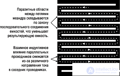
Figure 5. Elimination of the influence of mutual induction of conductors and parasitic capacitance in surface-mounted resistors
Given that the installation of surface-mounted resistors is carried out in stoves, resistor manufacturers pay great attention to the temperature curve of heating and cooling resistors. A typical temperature curve for soldering surface-mounted resistors is shown in Figure 6.
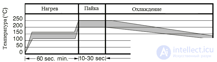
Figure 6. Temperature soldering curve of surface mounted resistors
Literature:

Comments
To leave a comment
Design and engineering of electronic equipment
Terms: Design and engineering of electronic equipment