Lecture
A common and erroneous practice is an attempt to use flowcharts to illustrate the algorithm at a low level (at the code level) —that is, an attempt to write code fragments in an artificial language into the circuit blocks. Such an approach is applicable only to programs organized according to a structural approach and cannot reflect, for example, an algorithm that is implemented in the interaction of abstractions with an object-oriented approach. For the purpose of describing algorithms, the interaction of parts of the system and the illustration of many other related things, there is a UML notation.
from 01/01/92
This standard applies to symbols (symbols) in schemes of algorithms, programs, data and systems and establishes the rules for the execution of schemes used to display various types of data processing tasks and means of their solution.
The standard does not apply to the form of records and symbols placed inside or near symbols and serving to clarify the functions performed by them.
The requirements of the standard are mandatory.
1. GENERAL PROVISIONS
1.1. Schemes of algorithms, programs, data, and systems (hereinafter referred to as schemes) consist of symbols having a given value, a brief explanatory text and connecting lines.
1.2. Schemes can be used at various levels of detail, and the number of levels depends on the size and complexity of the data processing task. The level of detail should be such that the various parts and the relationship between them are generally understood.
1.3. This standard defines symbols for use in data processing documentation, and provides guidance on the conventions for use in:
1) data schemes;
2) program diagrams;
3) system operation diagrams;
4) programs interaction schemes;
5) system resource schemes.
1.4. The standard uses the following concepts:
1) the main symbol is a symbol used in cases where the exact type (type) of the process or data carrier is unknown or there is no need to describe the actual data carrier;
2) a specific symbol is a symbol used in cases when the exact type (type) of the process or data carrier is known or when it is necessary to describe the actual data carrier;
3) scheme - a graphical representation of the definition, analysis or method of solving a problem, in which symbols are used to display operations, data, flow, equipment, etc.
2. DESCRIPTION OF CIRCUITS
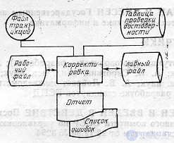
2.1. Data schema
2.1.1. Data schemes display the data path when solving problems and determine processing steps, as well as the various data carriers used.
2.1.2. The data scheme consists of:
1) data symbols (data symbols may also indicate the type of data carrier);
2) process symbols that should be performed on the data (process symbols can also indicate the functions performed by the computing machine);
3) line symbols indicating data flows between processes and (or) data carriers;
4) special characters used to facilitate the writing and reading of the scheme.
2.1.3. Data symbols precede and follow process symbols. The data scheme begins and ends with data characters (with the exception of the special characters indicated in § 3.4).
2.2. Scheme of the program
2.2.1 Schemes of programs display the sequence of operations in the program.
2.2.2. The program consists of:
1) process symbols indicating the actual data processing operations (including symbols defining the path to be followed with respect to logical conditions);
2) linear symbols indicating the flow of control;
3) special characters used to facilitate the writing and reading of the scheme.
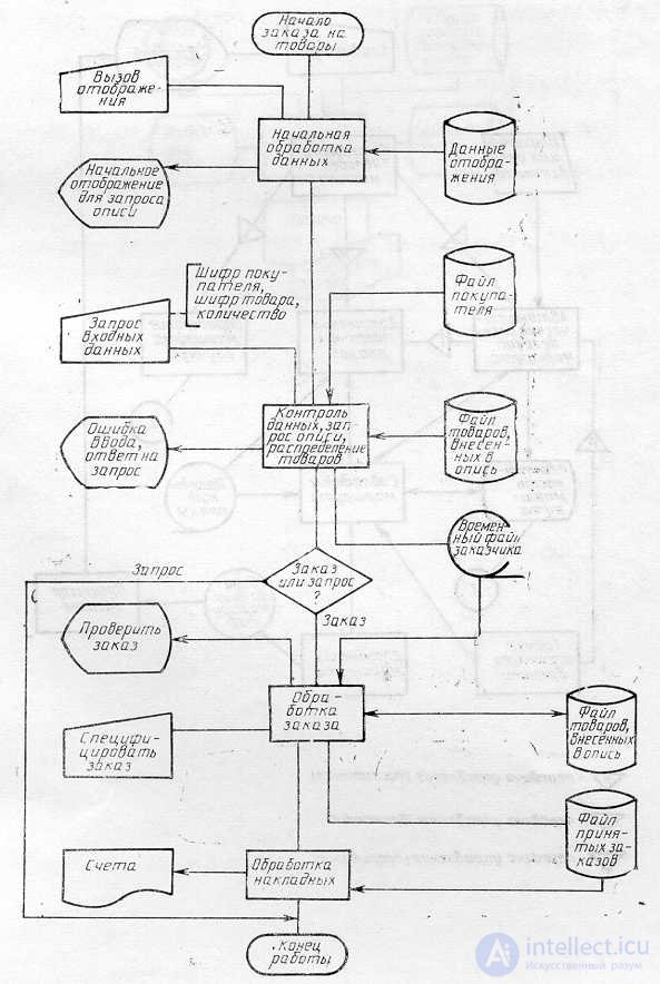
2.3. System operation diagram
2.3.1. Schemes of work of the system display management of operations and data flow in the system.
2.3.2. The system operation scheme consists of:
1) data characters indicating data availability (data characters may also indicate the type of data carrier);
2) process symbols indicating the operations to be performed on the data, as well as defining the logical path to be followed;
3) linear symbols indicating data flows between processes and (or) data carriers, as well as control flow between processes;
4) special characters used to facilitate writing and reading flowcharts.
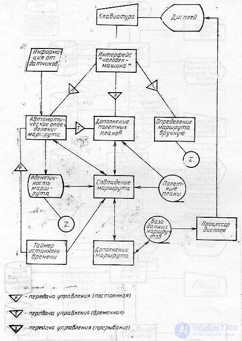
2.4. Program Interaction Scheme
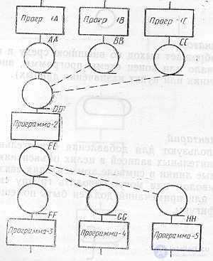
2.4.1. Program interaction patterns display the path of program activations and interactions with the corresponding data. Each program in the program interaction diagram is shown only once (in the system operation diagram, the program can be displayed in more than one control flow).
2.4.2. The program interaction scheme consists of:
1) data characters indicating data availability;
2) process symbols indicating the operations to be performed on the data;
3) linear symbols representing the flow between processes and data, as well as the initiation of processes;
4) special characters used to facilitate the writing and reading of the scheme.
2.5. System Resource Scheme
2.5.1. System resource diagrams display the configuration of data blocks and processing blocks, which is required to solve a task or a set of tasks.
2.5.2. The system resource plan consists of:
1) data symbols representing input, output and storage devices of the computer;
2) process symbols representing processors (central processors, channels, etc.);
3) linear symbols representing data transfer between input / output devices and processors, as well as transfer of control between processors;
4) special characters used to facilitate the writing and reading of the scheme.
Examples of schemes are given in the appendix.
3. DESCRIPTION OF SYMBOLS
3.1. Data characters
3.1.1. Basic data characters
3.1.1.1. Data
The symbol displays the data, the storage medium is not defined.

3.1.1.2. Memorized data
The symbol displays the stored data in a form suitable for processing, the storage medium is not defined.
3.1.2. Specific Data Symbols
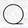
3.1.2.1. Random Access Memory
The symbol displays the data stored in the random access memory.
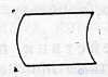
3.1.2.2. Serial Access Storage
The symbol displays data stored in a sequential-access storage device (magnetic tape, magnetic tape, tape cassette).
3.1.2.3. Direct Access Storage
The symbol displays the data stored in the storage device with direct access (magnetic disk, magnetic drum, flexible magnetic disk).

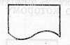
3.1.2.4. Document
The symbol displays the data presented on the media in a readable form (machine image, document for optical or magnetic reading, microfilm, tape roll with the final data, data entry forms).
3.1.2.5. Manual input
The symbol displays data entered manually during processing from devices of any type (keyboard, switches, buttons, light pen, barcode bars).
3.1.2.6. Map
The symbol displays data presented on a carrier in the form of a card (punched cards, magnetic cards, cards with readable marks, cards with a tear-off label, cards with scanned marks).

3.1.2.7. Paper tape
The symbol displays the data presented on the media in the form of a paper tape.

3.1.2.8. Display
The symbol displays data presented in human-readable form on a carrier in the form of a display device (screen for visual observation, indicators for entering information).
3.2. Process symbols
3.2.1. Key process symbols
3.2.1.1. Process
The symbol represents a data processing function of any kind (performing a specific operation or group of operations, leading to a change in the value, shape or location of information or to the definition of which one should move from several flow directions).
3.2.2. Process specific characters
3.2.2.1. Predefined process
The symbol displays a predefined process consisting of one or more operations or program steps that are defined elsewhere (in a subroutine, module).
3.2.2.2. Manual operation
The symbol represents any process performed by a person.
3.2.2.3. Training
The symbol displays a modification of a command or group of commands in order to influence some subsequent function (switch setting, modification of the index register or program initialization).
3.2.2.4. Decision
The symbol represents a switching type solution or function that has one input and a series of alternative outputs, one and only one of which can be activated after calculating the conditions defined inside this symbol. The corresponding calculation results can be recorded next to the lines representing these paths.
3.2.2.5. Parallel actions
The symbol displays the synchronization of two or more parallel operations.
_________________________________
_________________________________
Example.
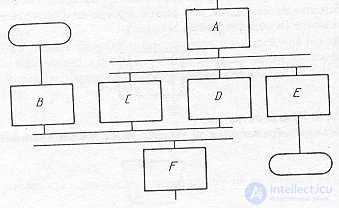
Note. Processes C, D, and E cannot start until process A is complete; similarly, process F must wait for the completion of processes B, C, and D, but process C may begin and (or) end before correspondingly start and (or) process D.
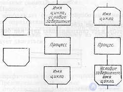
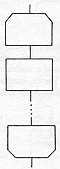
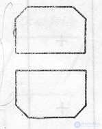
3.2.2.6. Cycle boundary
The symbol consisting of two parts, displays the beginning and end of the cycle. Both parts of the symbol have the same identifier. The conditions for initialization, increment, completion, etc. are placed inside the symbol at the beginning or at the end, depending on the location of the operation that checks the condition.
Example.
3.3. Line symbols
3.3.1 . Main line symbol
3.3.1.1. Line
Symbol displays data flow or control.
___________________________
If necessary or for increased readability, pointer-arrows can be added.
3.3.2. Line specific characters
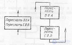
3.3.2.1. Transfer of control
The symbol represents the direct transfer of control from one process to another, sometimes with the possibility of a direct return to the initiating process after the initiated process completes its functions. The type of control transfer must be named inside the symbol (for example, request, call, event).

3.3.2.2. Link
The symbol indicates the data transmission over the communication channel.

3.3.2.3. Dotted line
A symbol displays an alternate relationship between two or more characters. In addition, the symbol is used to trace the annotated area.
Example 1
If one of a number of alternative exits is used as an input to a process or when an output is used as an input to an alternative process, these symbols are connected with dotted lines.
Example 2
The output used as an input to the next process can be connected to this input using a dashed line.

3.4. Special symbols
3.4.1. Connector
The symbol displays the exit to the circuit part and the input from another part of this circuit and is used to break the line and continue it in another place. The corresponding symbols - connectors must contain the same unique designation.

3.4.2. Terminator
The symbol indicates the output to the external environment and the input from the external environment (the beginning or end of the program diagram, external use and the source or destination of the data).
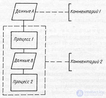
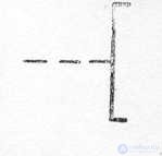
3.4.3. Comment
The symbol is used to add descriptive comments or explanatory notes for explanatory purposes or notes. Dotted lines in the comment symbol are associated with the corresponding symbol or can trace a group of symbols. The text of comments or notes should be placed near the bounding box.

Example.
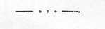
3.4.4. Pass
A symbol (three dots) is used in schemes to display the skip of a symbol or group of symbols in which neither type nor number of symbols is defined. The symbol is used only in or between line symbols. It is mainly used in diagrams depicting common solutions with an unknown number of repetitions.
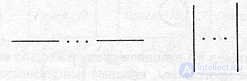
Example.
4. RULES OF APPLICATION OF SYMBOLS AND IMPLEMENTATION OF SCHEMES
4.1. Rules for the use of symbols
4.1.1. The symbol is intended to graphically identify the function that it displays, regardless of the text inside this symbol.
4.1.2. Symbols in the scheme should be evenly spaced. A reasonable length of connections and a minimum number of long lines should be followed.
4.1.3. Most characters are designed to enable the inclusion of text inside a character. Shapes of symbols established by this standard should serve as guidelines for actually used characters. Angles and other parameters affecting the appropriate shape of the characters should not be changed. Symbols should be as single as possible.
Symbols can be drawn in any orientation, but if possible, horizontal orientation is preferred. A mirror image of the shape of a symbol indicates the same function, but is not preferred.
4.1.4. The minimum amount of text necessary to understand the function of a given symbol should be placed inside this symbol. Text to be read should be written from left to right and from top to bottom, regardless of the direction of flow.
Example.
If the amount of text placed inside a symbol exceeds its size, use the comment symbol.
If the use of comment symbols may confuse or destroy the flow of the pattern, the text should be placed on a separate sheet and cross-referenced to the symbol.
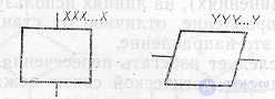
4.1.5. Character identifiers can be used in schemas. It is an identifier associated with a given symbol, which identifies the symbol to be used for reference purposes in other elements of the documentation (for example, in a program listing). The symbol identifier must be located on the left above the symbol.
Example.
4.1.6. Schemes can use character descriptions — any other information, for example, to display a special use of a cross-referenced character, or to improve the understanding of a function as part of a schema. The symbol description must be located to the right above the symbol.
Example.
4.1.7. In the schemes of the system, the symbols representing the data carriers in many cases represent input / output methods. For use as a reference to the documentation, the text on the diagram for characters displaying output methods should be placed on the right above the symbol, and the text for characters displaying input methods on the right below the symbol.
Example.

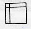
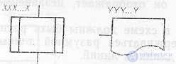
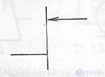
4.1.8.Schemes can use a detailed representation, which is indicated by a bar symbol for a process or data. The lane symbol indicates that there is a more detailed representation elsewhere in the same documentation set.
A symbol with a stripe is any symbol within which a horizontal line is drawn at the top. An identifier is placed between this line and the top line of the symbol, indicating a detailed representation of this symbol.
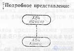
An end pointer character should be used as the first and last character of the detailed view. The first character of the end pointer must contain a link, which is also in the symbol with a bar.

4.2. Connection rules
4.2.1.Data streams or control flows in diagrams are shown as lines. Flow direction from left to right and top to bottom is considered standard.
In cases where it is necessary to make more clarity in the scheme (for example, when connecting), arrows are used on the lines. If the flow has a direction other than the standard, the arrows should indicate this direction.
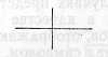
4.2.2.Crossing lines should be avoided in diagrams. Intersecting lines do not have a logical connection between themselves, therefore, changes in direction at the intersection points are not allowed.
Example.
4.2.3.Two or more incoming lines can be combined into one outgoing line. If two or more lines are combined into one line, the place of association must be shifted.
Example.
4.2.4.The lines in the diagrams must fit the symbol either on the left or on the top, and proceed either on the right or on the bottom. Lines must be directed to the center of the symbol.
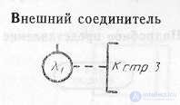
4.2.5.If necessary, lines in the diagrams should be broken to avoid unnecessary intersections or too long lines, and also if the diagram consists of several pages. The connector at the beginning of the gap is called the external connector, and the connector at the end of the gap is called the internal connector.
4.2.6. Links to pages can be given together with a comment symbol for their connectors.
Example.

4.3. Special conventions
4.3.1. Several exits
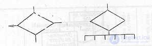
4.3.1.1. Several exits from the symbol should be shown:
1) several lines from this symbol to other symbols;
2) one line from a given symbol, which then forks into the corresponding number of lines.
Examples
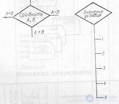
4.3.1.2. Each exit from the symbol must be accompanied by the corresponding condition values in order to show the logical path it represents, so that these conditions and the corresponding references are identified.
Examples
4.3.2. Recurring submission
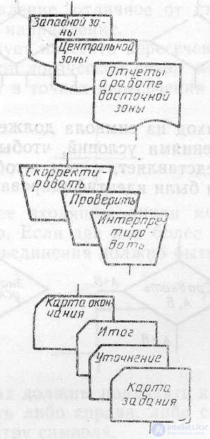
4.3.2.1. Instead of a single character with the corresponding text, several characters can be used with overlapping images, each of which contains descriptive text (using or generating several data carriers or files, making multiple copies of printed reports or punch card formats).
4.3.2.2. When several characters represent an ordered set, this ordering should be located from the front (first) to the back (last).
4.3.2.3. Lines can enter or originate from any point of overlapped characters, however, the requirements of clause 4.2.4 must be met. The priority or sequential order of several characters does not change by the point at which the line enters or comes from.
Example.
5. APPLICATION OF SYMBOLS
|
Symbol |
By name
the knowledge character |
Data schema |
Programming Scheme we |
System operation diagram |
Schema inter action visions of the prog- ramme |
Resource Scheme owls system we |
|
Data characters |
||||||
|
Main |
||||||
|
|
Data |
+ |
+ |
+ |
+ |
+ |
|
|
Remember
Called data |
+ |
- |
+ |
+ |
+ |
|
Specific combs |
||||||
|
|
Operational
memorized inspiring device |
+ |
- |
+ |
+ |
+ |
|
|
Remember
inspiring device with consequent accurate sample |
+ |
- |
+ |
+ |
+ |
|
|
Remember
inspiring device with straight by access |
+ |
- |
+ |
+ |
+ |
|
|
Document |
+ |
- |
+ |
+ |
+ |
|
|
Manual
input |
+ |
- |
+ |
+ |
+ |
|
|
Map |
+ |
- |
+ |
+ |
+ |
|
|
Paper
tape |
+ |
- |
+ |
+ |
+ |
|
|
Display |
+ |
- |
+ |
+ |
+ |
|
Process symbols |
||||||
|
Main |
||||||
|
|
Process |
+ |
+ |
+ |
+ |
+ |
|
Specific combs |
||||||
|
|
Prevention
divided process |
- |
+ |
+ |
+ |
- |
|
|
Manual
operation |
+ |
- |
+ |
+ |
- |
|
|
Training |
+ |
+ |
+ |
+ |
- |
|
|
Decision |
- |
+ |
+ |
- |
- |
|
|
Paral-
action |
- |
+ |
+ |
+ |
- |
|
|
Cycle boundary |
- |
+ |
+ |
- |
- |
|
Line symbols |
||||||
|
Main |
||||||
|
|
Line |
+ |
+ |
+ |
+ |
+ |
|
Specific combs |
||||||
|
|
Transfer control
of |
- |
- |
- |
+ |
- |
|
|
Link |
+ |
- |
+ |
+ |
+ |
|
|
Dotted line-
naya line |
+ |
+ |
+ |
+ |
+ |
|
Special symbols |
||||||
|
|
Connect
tel |
+ |
+ |
+ |
+ |
+ |
|
|
Term-
torus |
+ |
+ |
+ |
- |
- |
|
|
Comme-
tarie |
+ |
+ |
+ |
+ |
+ |
|
|
Pass |
+ |
+ |
+ |
+ |
+ |
Note. The "+" sign indicates that the symbol is used in this scheme, the "-" sign is not used.
ATTACHMENT
Help
EXAMPLES OF EXECUTION OF SCHEMES
1. Data scheme
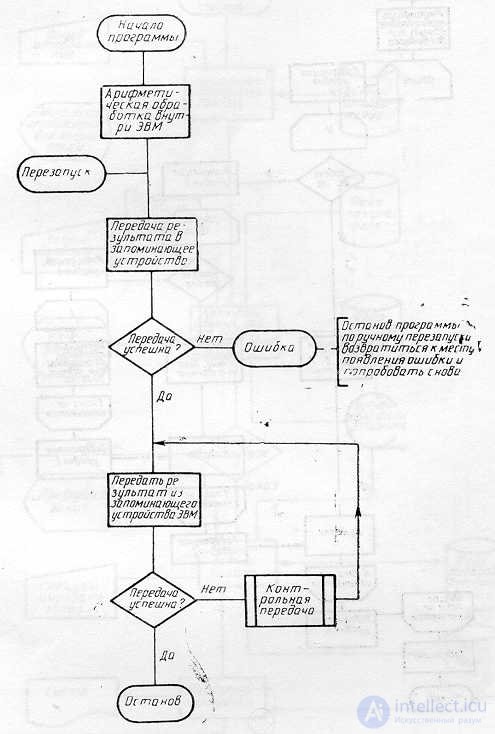
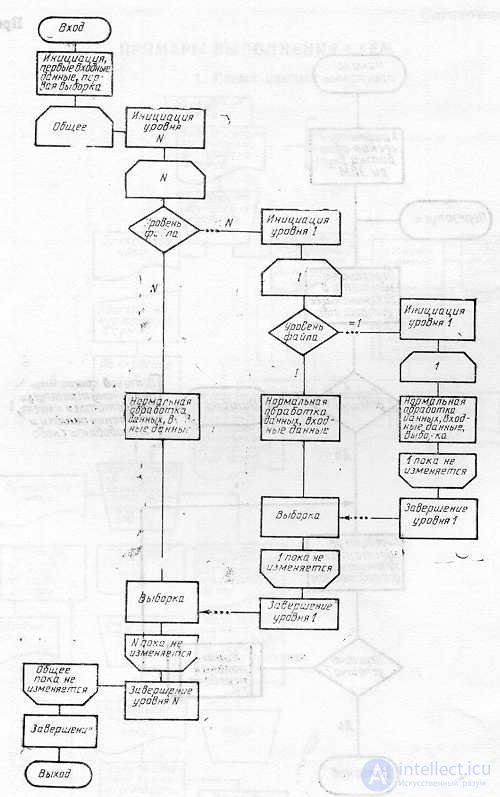
2. Schemes of the program
Example 1
Example 2
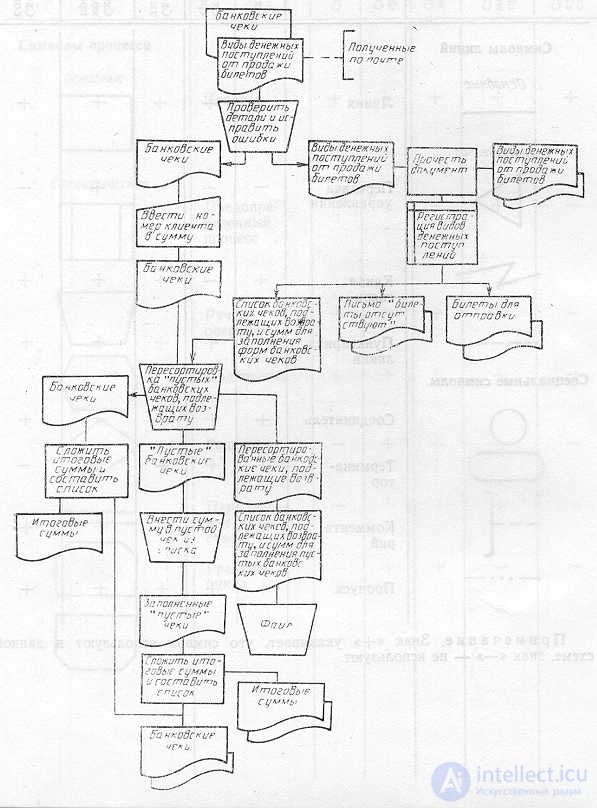
3. Scheme of the system
4. Program interaction scheme
5. Scheme of system resources


Comments
To leave a comment
Algorithms
Terms: Algorithms