Lecture
1. Objects of binary logic.
Binary (binary, mathematical, formal) logic considers logical statements (judgments, statements) as objects.
Any statement within its framework can be either true (true) or false (false), - "no third is given."
We agree in the first case to assign the value of "logical one" to the statement, and in the second case - to "logical zero".
Now, any statement can be viewed as a kind of "logical variable" with values of 1 or 0. For example, let the statement "Life on Earth exist" correspond to a logical variable with the name x. Then x = 1, etc.
For complex combinations of statements, it is possible to define functions (operations, actions) on logical variables. Thus, there is a "algebra of logic" or "Boolean algebra" - on behalf of the creator of such an algebra, English mathematics and the logic of Buhl (Bool) with their actions, properties and theorems. Boolean algebra is the logical basis of digital technology.
We will represent logical functions simultaneously in several equivalent forms:
Models in Mathcad 2000, MS Excel 2000 and Electronics Workbench 5.12 will be used for the algebraic representation of logical functions, their truth tables, timing diagrams and logic diagrams.
2. Some logical functions.
2.1. Functions of one logical variable (unary).
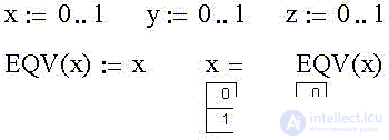
Formally, you can either agree with any statement or not. The first case corresponds to the function "Logical identity (equivalence)" .
In Mathcad, we define integer variables x, y, and z, taking the values 0 or 1. We also define the above function of the variable x as EQV (x):
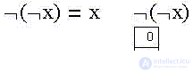
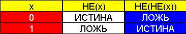
We now define the second of the two possible unary functions "Logical negation (NOT, NOT, inversion)" as NOT (x):
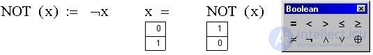
The figure also shows the panel of logical (boolean) operators Mathcad.
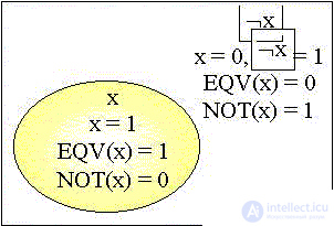
Let us draw a Venn diagram common to two functions:
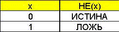
Let's create an Excel truth table for the logical negation function:
Circuit images in Logic Gates Electronics Workbench of the functions considered:
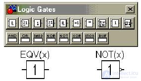
The second element is called the inverter (pay attention to the image of the inverse output of the element). The figure also shows the panel of logical elements.
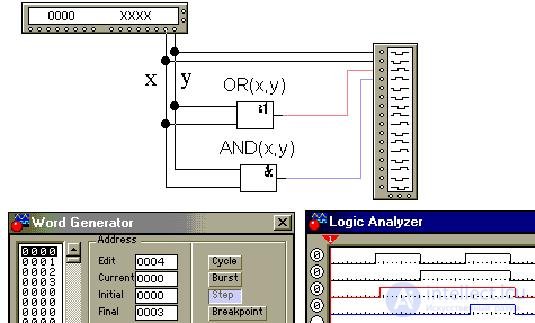
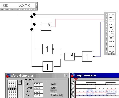
Let's build in Electronics Workbench a time diagram on virtual models of elements, for which we will get input values from the word generator (Word Generator), then supplying them and output values to a logic analyzer (Logic Analyzer):
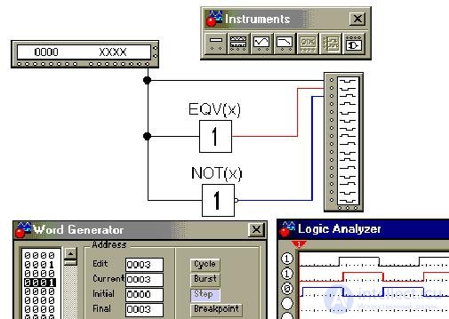
In a 16-bit generator, words every 4 binary digits (nibbles) are encoded with a hexadecimal digit from 0 to F. In our case, for example, the value of the variable x = 1 in the generator corresponds to the binary code 0000 0000 0000 0001 and the hexadecimal code 0001, as in the figure above.
The figure also shows the toolbar.
2.2. Functions of two logical variables (binary).
Of the more than a dozen such functions, we consider only two: each of them, in combination with logical negation, forms the so-called “logical basis”, sufficient for the synthesis of the remaining functions, as well as arbitrary logical automata.
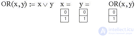
We define the binary function "Logical addition (OR, OR, disjunction)" as OR (x):
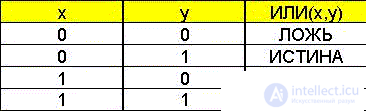
Create the corresponding truth table in Excel:
Suppose that variable x corresponds to the statement “Mom bought a fish” and variable y - “Dad caught a fish”, then their logical sum, obviously, corresponds to the statement “Vaska's cat has a fish for dinner today!”.
In the Venn diagram, the last statement is true on a set of points belonging to either x or y (the figure-eight area is the union of x and y):
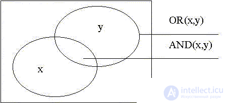
But the situation when x is the statement “Ticket purchased”, and y - “Not late in the cinema”, gives only with the simultaneous truth both one and the other truth of the statement “Watch a movie”. The latter is true on the set of points belonging to both x and y on the Venn diagram above (the “leaf” area is the intersection of x and y).
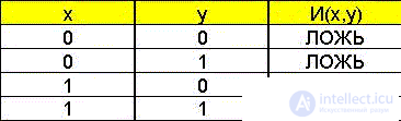
We define such a binary function, - it is called "Logical multiplication (AND, AND, conjunction)" , - as AND (x):
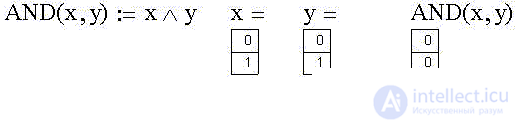
Create the corresponding truth table in Excel:
We will get a timing diagram on the virtual models of the disjunctor and conjunctor , noting that in the table above in the rows of variable values from top to bottom there is a binary account from 00b = 0d = 0h to 11b = 3d = 3h (here: b - binary, binary, d - decimal, decimal and h - hexadecimal, hexadecimal representations of numbers):
3. Logical identities.
3.1. Logical identities with one variable.
The first in a series of identities is the result of the double application of the unary operation of negation to a variable — the “law of negation of negation”: the negation of the negation of an affirmation is identical with the statement . Example: the statements "I affirm" and "I do not affirm" are obviously equivalent.
On the Venn diagram, the first negation of a variable takes out the region where it is true, the second negation returns to it, since the "third" possibility simply does not exist.
Here is the proof in the Excel spreadsheet:
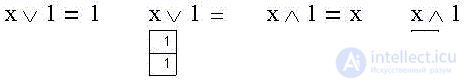
The next group of identities represents the results of applying binary operations to a logical variable with 0, with 1, with the variable itself and with its negation.
If we recall that the Venn diagram of a notorious lie has zero area, then it is obvious that combining with it "will not give anything new", and the intersection with notorious lies has its same zero area:

Combining this statement with any possible true statements coincides with them all, while the intersection with all possible true statements "cuts out" the given (including, obviously, even if it is false):
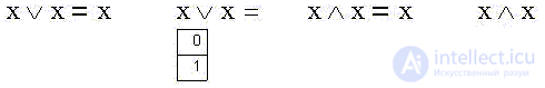
It is also obvious that the union and intersection of the statement with itself is equivalent to the statement itself (the case of tautology):
Finally, the logical sum of the statement and its negation (one of the two is true) is true, just as their product is false (their simultaneous truth):
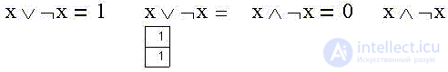
“The patient is more alive than dead” (either alive or not alive) is a deliberate truth. And vice versa: "both alive and not alive" is a deliberate lie.
3.2. Logical identities with three variables.
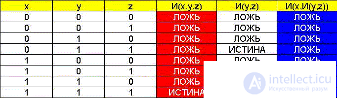
Examples of combination (associative) properties in the algebra of logic:
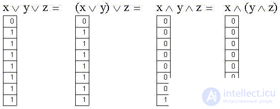
In practice, these properties allow replacing multi-input logic elements of circuits with sequentially used two-input ones, for example:

When proving with the help of the truth table, a separate column AND (y, z) appeared, corresponding to the action in brackets:
Distributive (distributive) properties are more interesting - they show that (unlike "ordinary" algebra), logical addition and multiplication operations in formal logic are absolutely symmetric: if in both parts of an identity we replace disjunction with a conjunction and vice versa, we again get the identity:
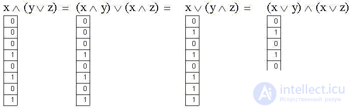
We are talking about the disclosure of brackets, moreover, if both parts of the first identity in the “ordinary” algebraic notation have a completely familiar form:
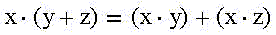
the second identity, which is obtained from the symmetric replacement in the first addition operations by multiplication and vice versa, looks very unusual:
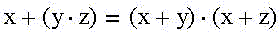
For clarity, we represent the left and right sides of this identity on separate Venn diagrams:
3.3. The de Morgan identities.
Practically, the most interesting is not the symmetric replacement of sums by works and vice versa, namely, either replacing only sums with works, or just the opposite.
The corresponding identities are called de Morgan identities (rules). Consider the case of two variables.
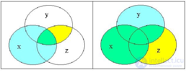
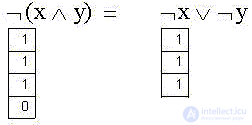
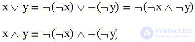
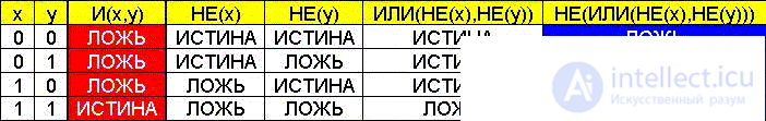
1) The negation of the logical sum of the statements is equivalent to the product of their negations:
2) The negation of the logical product of statements is equivalent to the sum of their negations:
Using the law of negation of negation and the above identities, one can get rid of “pure” sums and works:
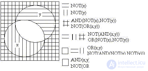
We present the Venn diagram that is common for four identities:
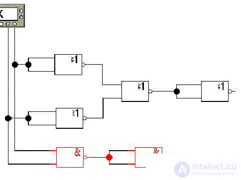
Let us show the validity of the last identity in Electronics Workbench:
The same in Excel:
3.4. Logical (boolean) bases.
It is easy to show that combining the inputs of a disjunctor with a negation or a conjunctor with a negation (left parts of de Morgan identities) gives an inverter, so any possible logical operation can be represented as a combination of logical complexes 2-OR-NOT or 2-AND-NOT, which are thus logical bases .
Let us show, for example, the right-hand side of the just considered identity (the replacement of a logical product) in the 2-OR-NOT basis, and the left-hand side, the product itself, in the 2-AND-NO basis (lower scheme):
4. Synthesis of combinational logic circuits (functions).
4.1. Definition of the formula of a circuit (function) by its truth table.
Imagine, in the role of Buridan's donkey, the stupid cat Vaska, who is unable to choose between mother and father's fish and left without dinner:
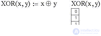
The XOR (x, y) function is called the "exclusive OR" (exclusive OR), as well as the "modulo 2 sum" (the sum of the values of the variables x and y in the low-order bit).
Let's display the given truth table of the logical function “Foolish Cat Vaska”, in the form of a formula - the logical sum of the products of variables (or their negations), for which XOR (x, y) takes the value of a logical unit. To do this, add columns of values of all possible products to the table and select the necessary ones:
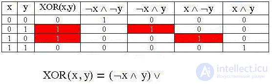
The resulting formula is the perfect disjunctive normal form (SDNF) of a logic function defined by the truth table:
The table above can be represented as follows:
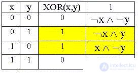
The fourth column shows the products equal to the logical unit for the corresponding values of the variables. The SDNF includes works "side by side" with units of a logical automaton defined by the truth table.
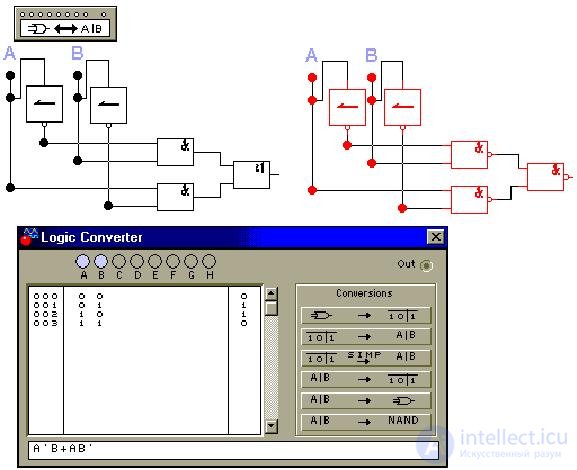
Let us define in the logical converter (Logic Converter) a truth table corresponding to the logic function discussed above; we obtain for it a logical formula (SDNF), a logic circuit, and also a circuit in the 2-AND-NOT basis:
4.2. Minimization of logic functions using analytical transformations.
The idea is to go from the PDNF to DNF with a minimum of terms, and the number of factors in each term should also be minimal (get rid of "perfection"). In other words, to minimize the number of variables and operations in MDNF.
The function can be simplified directly using algebraic transformations using the above identities (which is not always easy with a large number of variables), as well as by transforming the state table of the function.
Let us consider both minimization options using the example of the function of three logical variables defined by the truth table below:
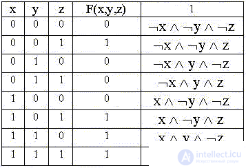
We write the PDNF:

At first we will transform the right part "unsuccessfully". We put out for brackets the product of x and z only from the second and fourth terms of conjunctions:

Let's use already known identities:

and we will get further not simplified, "dead-end" DNF (but not "minimal"):

There are only three conjunctions in DNF, and in the second there is no variable y.
Now we note that in the first and second conjunctions of the PDNF, the product of negation y with z can be taken out of the brackets, and in the third and fourth, the product of x and y:

Taking advantage of the identities

we get the minimum DNF:
4.3. Minimization of logical functions using a graphical representation of the n-dimensional cube.
When the number of variables is no more than 4, all possible dead ends and the minimal forms themselves can be simply seen on a spatial diagram — an n-dimensional (in our case, 3-dimensional) cube — a Cartesian graph, where their possible axes are displayed on the axes corresponding to the variables States (0 or 1). The state points at which (according to the truth table) the function takes single values will be represented by larger ones:
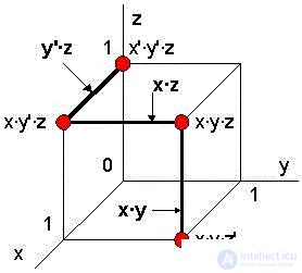
The dash to the right of the variable name means its negation; for a conjunction, the usual multiplication symbol (as in the Electronics Workbench logical converter) is used.
The edge formula along the axis of a variable does not contain this variable, since the value of the function on the “glued” vertices does not depend on the value of this variable, which corresponds to the operation of taking out the common factor. For example, the edge x · z connects the points x · y '· z and x · y · z:
(x · y '· z) + (x · y · z) = x · z · (y' + y) = x · z
According to the diagram, the minimization problem is reduced to the union of the maximum of the vertices on which the function takes unit values to the minimum of the edges. In our case, these are two edges y '· z and x · y, the “glued” four vertices.
The “unsuccessful” minimization variant corresponds to the choice of one edge x · z and the “remaining” vertices x ′ · y ′ · z and x · y · z ′.
Other dead-end DNFs are obvious: two variants of adjacent edges plus one remaining vertex and three edges. All options are not minimal. To obtain the indicated variants of dead-end forms analytically, one must use the known identity.
x + x = x
and write down the "necessary" conjunction twice. For example, the diagram shows a DNF of two edges and a point:
F (x, y, z) = x · y + x · z + x '· y' · z
We obtain it analytically by writing the conjunction x · y · z twice (underlined):
F (x, y, z) = x '· y' · z + x · y '· z + x · y · z' + x · y · z + x · y · z =
= x '· y' · z + x · y · (z '+ z) + x · z · (y' + y) =
= x '· y' · z + x · y + x · z
Note that in the case when the selected vertices form a cube face, the formula of such a face consists of only one variable (or its negation), the axis of which intersects this face.
Let, for example, be given SDNF some function G (x, y, z):
G (x, y, z) = x · y '· z' + x · y · z + x '· y · z + x' · y · z '+ x · y · z'
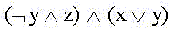
Here the conjunctions from the 2nd to the 5th form the face, the formula of which is y:
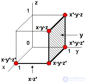
The formula for the edge that has glued the vertices x · y '· z' and x · y · z 'is x · z'. So the minimum DNF is equal to:
G (x, y, z) = x · z '+ y
The spatial diagram "maintains" the representation and the 4th variable, the negation of which is determined on the vertices of the inner cube inserted into the outer cube. The values of the other variables are identical on both cubes:
4.4. Минимизация логических функций методом Куайна - Мак-Класки.
Вернемся теперь к функции F(x,y,z). Заметим, что объединение двух смежных вершин в ребро, соответствующее выносу за скобки общего множителя, в таблице истинности означает объединение двух строк в одну. В комбинируемых строках должны совпадать все значения переменных, кроме одной - сравниваемые строки отличаются на одну единицу . Значение "не совпавшей" переменной безразлично и может быть обозначено крестиком "x". Например, указанные ниже две строки (ребро y'·z)
можно заменить одной строкой:
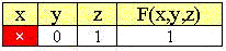
т. к. в этой строке значение переменной x не влияет на единичность функции.
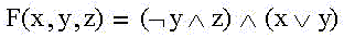
Минимизируем таблицу истинности нашей функции (см. ниже).
Можно ожидать, что СДНФ максимально свернутой таблицы истинности и будет минимальной ДНФ. Поэтому добавим в минимизированной таблице столбец конъюнкций "существенных" переменных.
 =>
=> 
В последней таблице СДНФ совпала с минимальной ДНФ:
Получим тот же результат, последовательно шаг за шагом применяя общий метод Куайна - Мак-Класки (Quine - McCluskey) минимизации логических функций.
Step 1.
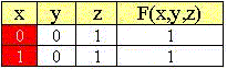
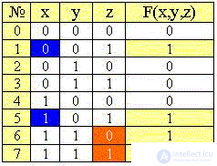
Запишем ещё раз таблицу истинности для функции F(x,y,z) с указанием единичных конъюнкций- минтермов и количества единиц в значениях переменных:
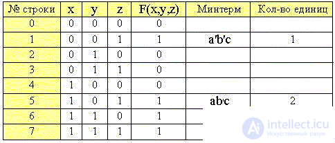
Step 2.
We divide the table into groups of rows (minters) with the same number of ones , removing from the table the rows with a zero value of the function:
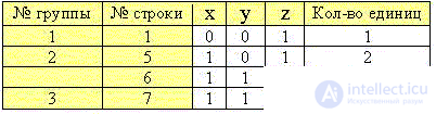
Step 3.
Let's compare the sets of values of variables of each previous group with the next and combine the lines with a common factor, as before:
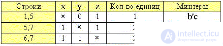
Step 4.
We will be convinced in the absence of minterms with common positions of "crosses" , i.e., the impossibility of further simplification.
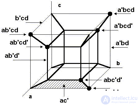
Step 5.
Note also that the resulting DNF is not minimal and corresponds to three edges in the spatial diagram:
F (x, y, z) = b'c + ac + ab.
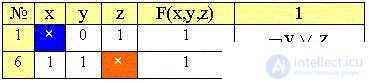
Удалим поэтому из таблицы избыточную среднюю комбинацию из строк 5 и 7, так как строка 5 выше уже сгруппирована с 1-й, а строка 7 - ниже с 6-й. Получаем окончательную минимальную таблицу комбинаций строк и соответствующую ей минимальную ДНФ:
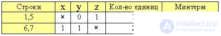
F(x,y,z) = b'c + ab.
В качестве упражнения минимизируем функцию S(a,b,c,d) 4-х переменных, а результат дополнительно проверим в логическом конверторе Electronics Workbench (программа которого реализует алгоритм именно данного метода).
Саму же функцию S(a,b,c,d) зададим графически как "состоящую" из двух граней и отрезка. В таблице слева от чертежа указаны "координаты" крупных точек-вершин, на которых функция принимает единичные значения, или конъюнкции, входящие в СДНФ:
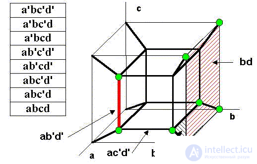
S(a,b,c,d) = a'bc'd' + a'bc'd + a'bcd + ab'c'd' + ab'cd' + abc'd' + abc'd + abcd
S(a,b,c,d) = ab'd' + bc' + bd
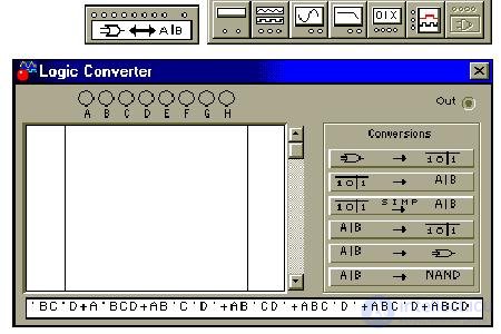
Для проверки в логическом конверторе перепишем правую часть СДНФ в верхнем регистре, прописными буквами:
A'BC'D'+A'BC'D+A'BCD+AB'C'D'+AB'CD'+ABC'D'+ABC'D+ABCD
скопируем и вставим в строку формулы конвертора:
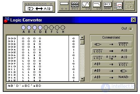
Теперь восстановим по формуле таблицу истинности (4-я кнопка) и упростим таблицу, получив в строке формулы минимальную ДНФ (3-я кнопка):
Минимизируем функцию S(a,b,c,d) методом Куайна - Мак-Класки.
1. Создадим таблицу истинности функции S(a,b,c,d):

2. Сгруппируем минтермы по количеству в них единиц:
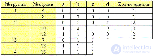
4. Произведем первое объединение строк каждых предыдущих и последующих групп:
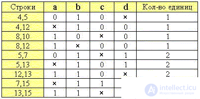
5. Объединим строки с совпадающими позициями "крестиков":
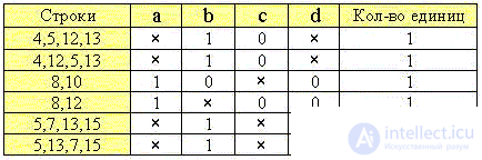
6. Из двух строк с идентичными значениями минтермов оставляем только одну:
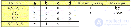
7. Обращаем внимание на то, что третий минтерм избыточен (лишнее ребро ac'd' на пространственной диаграмме), т. к. 8-я строка уже вошла в комбинацию с 10-й строкой (2-й минтерм), а 12-я - в комбинацию с 4-й, 5-й и 13-й строками (1-й минтерм). Поэтому удаляем третью строку таблицы и записываем минимальную СДНФ:
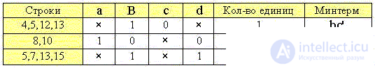
S(a,b,c,d) = bc' + ab'd' + bd.
Умение создавать и минимизировать логические функции имеет огромное значение при проектировании устройств цифровой электроники.

Comments
To leave a comment
Discrete Math. Set theory. Graph theory. Combinatorics.
Terms: Discrete Math. Set theory. Graph theory. Combinatorics.