Lecture
Frequency converters (converters) shift the signal spectrum from one frequency range to another while maintaining its structure.
You can receive programs transmitted through UHF channels only on TVs equipped with special channel selectors. The channel selector of decimeter waves (ACS) directly converts the frequencies of the UHF television channels to the intermediate frequency of the image and sound. When directly converting television signals UHF, the frequency of the local oscillator fr SKD above the carrier frequency of the image of the received TV channel at 38 MHz:
fr = fni + fpchi (4-12)
where fnu is the carrier frequency of the image of the received channel;
php- intermediate frequency of the image signal (38 MHz).
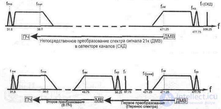
Fig. 4.42. Frequency spectrum transfer in converters
The signal converted by the ACS unit is fed to the input of the meter selector channel selector mixer (SCM), which, when receiving UHF channels, performs the function of an IF amplifier. For television receivers without UHF blocks, converters are used that provide reception and pre-conversion of the UHF channels into one of the channels of the meter range. In this case, the converted signal is fed to the input of the meter range selector (SCM), where it is amplified and the second conversion occurs.
This method of reception (Fig. 4.42) determines the frequency of the local oscillator converter, which must be lower than the carrier frequency of the image of the received UHF TV channel by the value of the carrier image of the meter TV channel (on which TV programs of the UHF band will be received).
fr = fni (DMV) - fni (MV), (4.13)
where fni (UHF) is the carrier frequency of the image of the reception channel of the UHF band;
fni (MW) is the carrier frequency of the image of the receiving channel of the meter range.
Converters can be built into the TV, installed as part of fixed equipment in a collective reception system, or made in the form of a set-top box - the channel selector in the UHF range. The prefix - the selector is designed to work with television receivers meter range of any type and class without additional alteration.
4.4.1. CTC Converter (OTU-3. 2)
KTK Converter is designed for round-the-clock work as part of the unified television equipment OTU-3. 2 for the system of collective reception of television SKPT and is designed for the selection, transformation and amplification of one of the television channels of the UHF wave band in the signals of the frequency channel of the meter range.
Converter Parameters Gain at the channel center frequency, dB ....................................... 30 ± 5
Irregularity of the frequency response in the channel frequency band, dB, not more than ................................. 2
SWR at the input and output of the converter in the frequency band
± 4 MHz of the average frequency transmission, no more ......................................... ....... 1, 7
Selectivity on the mirror channel, dB, not less ....................................... 50
Noise ratio, dB, not more than ........................................... ................................ 12
Signal strength of the local oscillator penetrating the converter input,
mkw, no more .............................................. .................................................. ............ 0, 05
The field strength of the radio signal from the radiation of the local oscillator converter
at a distance of 3 m, dB mV / m. no more................................................ .................... 66
Power consumption, W, not more than ........................................... ........................... 15
The converter is made in the form of a ruler, the design of which allows its use as part of the unified television equipment OTU-3. 2
The circuit diagram of the KTK-41/6 converter is shown in fig. 4. 44. The converter consists of a three-cavity coaxial input filter (W1, W2, W3), a directional E4 coupler (a device for combining signal power and a local oscillator), a mixer with a VT1 transistor, a heterodyne with a VT4, VT3 transistor. Input
the filter is made on three segments of short-circuited coaxial lines. The high-frequency signal is introduced into the filter using an inductive E1 coupling loop, which excites the W1 line.
The filter lines are quarter-wave coaxial resonators with capacitors at the open ends. Their length is somewhat less than a quarter of the wavelength corresponding to the upper boundary of the decimeter range. The resonators are tuned to the specified channel with the help of trimming capacitors C1 С2 СЗ, connected to

Fig. 4. 43. Appearance of CPC converter
open ends of lines. The used design allows tuning the filter to any of the channels in the 470 ... 638 MHz range (21-41 TV channels).
The coupling of the input filter resonators with the generator is carried out with the aid of the E2 coupling loop, and the coupling between the resonators through holes (connection windows) cut in the common walls of the resonators. From the output of the filter, the signal is fed through capacitor C4 to one of the arms of the directional coupler (BUT) E4, to the other arm of which through the capacitor C7 receives the local oscillator voltage. The directional coupler has a transient attenuation of about 10 dB and is made in the form of two electromagnetic-coupled lines wound on a metal tube.
The use of BUT to add power to the signal and the local oscillator reduces the power level of the local oscillator penetrating the input
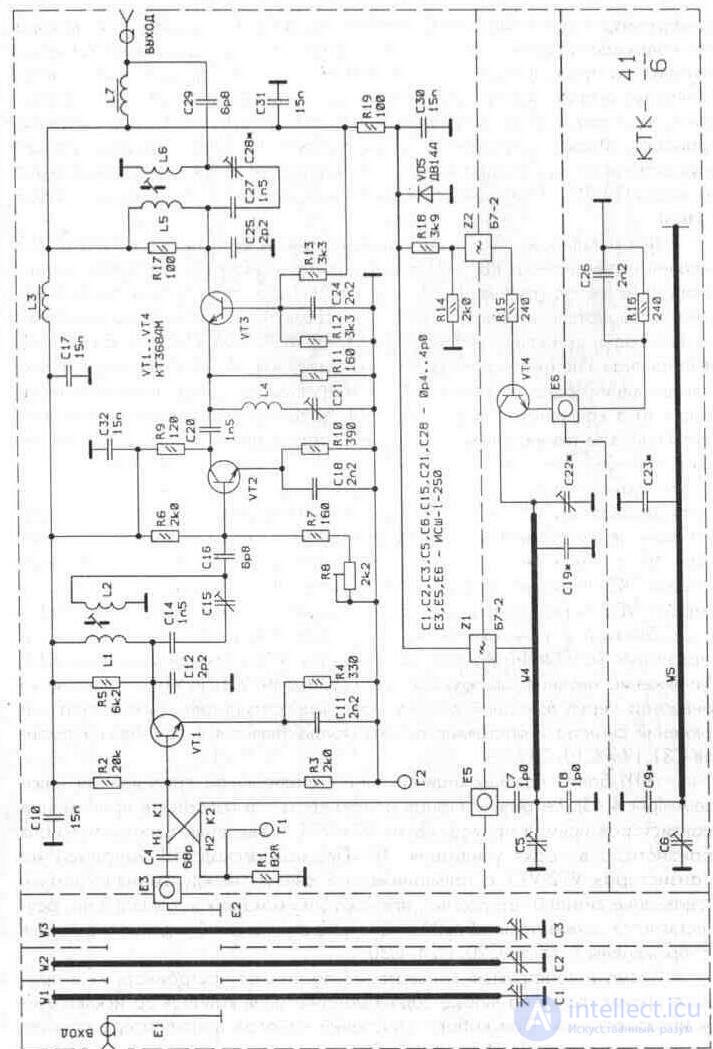
Fig. 4. 44. Schematic diagram of the converter KTK-41/6
converter, as well as simplify the process of setting up the converter. From the output of the signal voltage and the local oscillator are fed to the input of the mixer, made on the transistor VT1. The load of the mixer is a filter on coupled capacitive coupling circuits (the first - L1C12 is made in the form of a parallel circuit, and the second - L2C16 - in the form of serial). The filter is tuned to the frequency band of the channel in which the conversion is performed. From the output of the mixer, the signal arrives at the input of the PSU (VT2 - according to the scheme with a common emitter, VT3 - according to the scheme with a common base).
To adjust the gain of the converter in the base circuit of transistor VT2 included potentiometer R8. To reduce the local oscillator power, which penetrates the converter output, the series circuit L4C21 tuned to the local oscillator frequency is connected to the collector circuit of this transistor. The local oscillator is made on the transistor VT4 according to the scheme with a common base. Its resonant system consists of two coaxial lines connected through a communication window, one of which (W4) is equivalent to a half-wave line and is connected to the collector of the transistor VT4, and the other (W5) is equivalent to a quarter-wave line and is connected to the feedback circuit. Due to the relatively weak coupling of the line of the W5 resonator with the W4 line and the emitter circuit of the transistor VT4, it is possible to obtain a sufficiently high Q of the W5 resonator, which makes it possible to stabilize the generation frequency. To increase the stability of the natural resonant frequency of the resonator W5, a C23 capacitor with a negative TKE is connected to the resonator line. Power to the collector of the transistor VT4 is supplied from the Zener diode VD5 through the filter Z1 connected to the line of the resonator W4 at a point close to the voltage node. To eliminate the parasitic oscillations in the heterodyne circuit, a resistor R15 is included in the base of transistor VT4. The supply voltage as well as in UTD and UTK amplifiers is supplied to the converter through the high-frequency output connector. Separation of the voltage signal and DC by using the elements of C31, L7 and C10, C17, L3.
CTC later modifications performed according to the diagram below (Fig. 4. 45). Its distinctive feature is the use of direct conduction transistors (VT1-VT4) and the introduction of an additional transistor in the path of the IF amplifier. The first IF cascade is made of transistors VT2-VT3 with galvanic coupling between the transistors. The suppression of the signal of the local oscillator penetrating the converter output is carried out by the elements L9. C29. To eliminate the excitation of the IF amplifier, capacitors C20, C24, SZ0 are used.
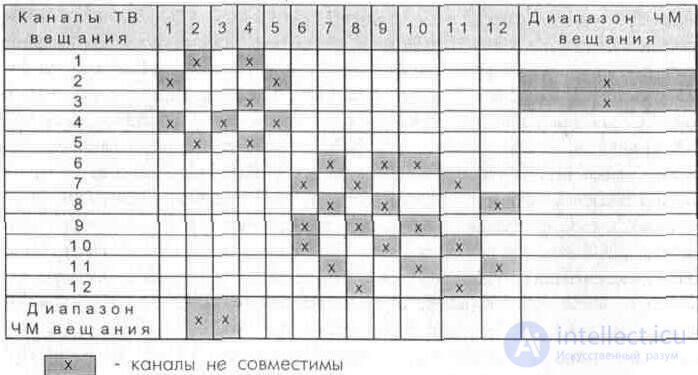
The design and construction of the converters allow you to adjust them in the production process to any given combination of channels except incompatible ones. When choosing combinations of channels in the converter, you should consider the data table. 4. 7 and 4. 8 [6. five].
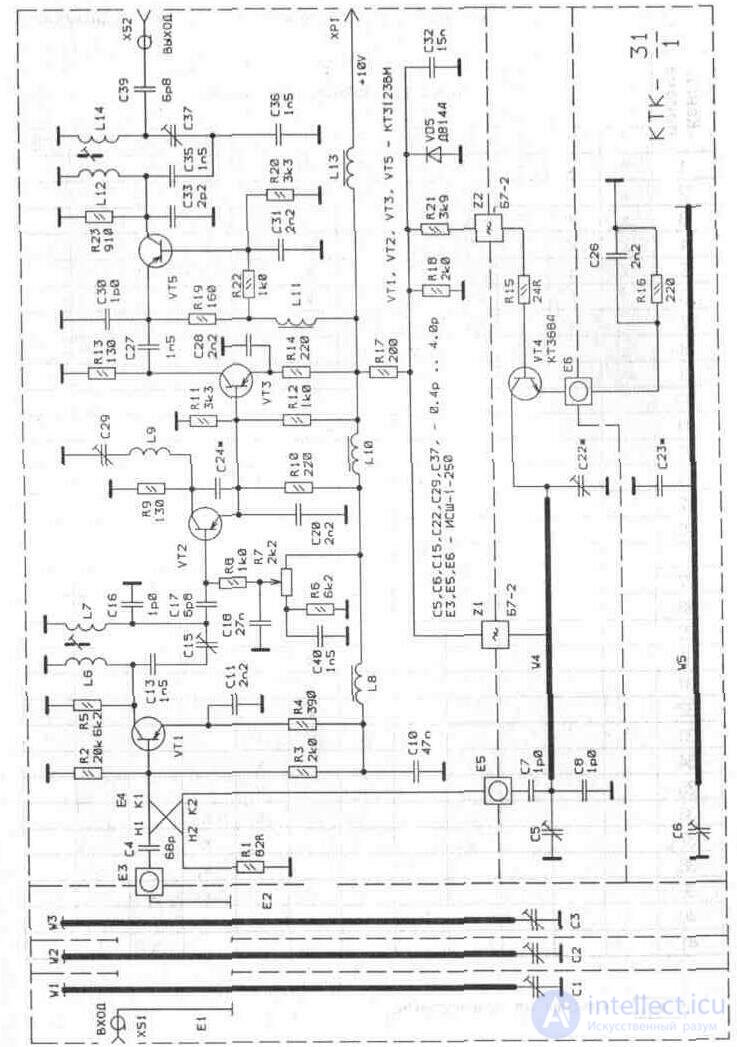
Fig. 4. 45. Schematic diagram of the converter KTK-31/1
Table 4. 7. Limitations when choosing channel combinations
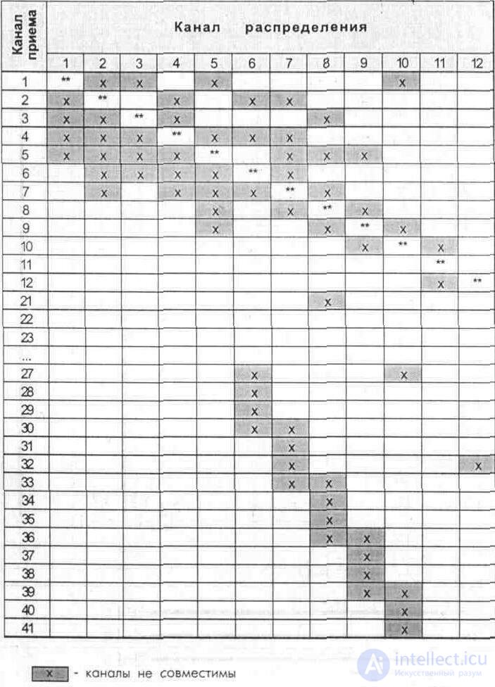
Table 4. 8. Limitations imposed by the presence of mutual interference in multi-program broadcasting conditions
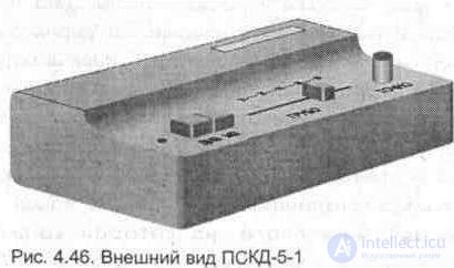
4.4.2. Prefix - selector channel decimeter range PSD-5-1 ("Kaluga", "Orbit", "Rostov-Don", "Khmelnitsky")
Specifications
Frequency range, MHz ............................................. .............. 470 ... 640
Prefix input, (Rin = 75 Ohms) ......................................... ............................ asymmetrical
Voltage transmission ratio, dB
at f = 470 MHz ............................................. ................................................ 0
at f = 640 MHz ............................................. ................................................. + b
Power consumption, W, not more than ........................................... ............ five
The prefix is designed to receive signals from the decimeter range (21-41) and convert them into signals of the meter range 1 or 2 channels. Structurally, the prefix is made in the form of a functionally complete structure, inside which the network is located
transformer, U1 stabilization unit, U2 radio path unit, control and switching controls. The mains voltage to the PDKD-5-1 unit (Fig. 4. 47) comes from switch B16, while switch B1a switches the signal from the output
Converter to the antenna socket XS3 (TV). The radio channel block U2 (converter) contains two stages - RF amplifier (radio frequency amplifier) and frequency converter. A high-pass filter (HPF) L1C1L2C2 is turned on at the UHF input; providing frequency suppression signals meter range. SZ capacitor improves the matching of the radio frequency amplifier with the highpass filter. The RF amplifier is assembled on a high-frequency transistor VT1 according to a common base circuit, which ensures good agreement with the antenna impedance (75 Ohms). The collector load VT1 is a dual-circuit bandpass filter consisting of half-wave coaxial lines L6, L 10 shortened by C9, C 10, C 11, C 12 capacitors at one end of the line and VD1, VD2 capacitors at the other. The connection between the circuits is provided by a short-circuited loop L8, placed in the cracks of the metal partition between the 2nd and 3rd sections. Such a connection is equivalent to an inductive connection between the coils of two circuits. The adjustment of the band-pass filter over the frequency range is provided by applying a bias voltage to the varicaps along the R3, L5, R4, L12 circuit from contact 3 (Un). The tuning elements at the low-frequency end of the range are short-circuited coupling loops L7, L9. The gain of the RF amplifier is regulated by changing the voltage of the “switchgear switchgear” supplied to the base of the transistor VT1 through R2 from contact 2. The converter is assembled on the transistor VT2 according to the common base circuit. In this scheme, the mixer and the local oscillator are combined. The voltage allocated in the bandpass filter through the loop connection L11, is fed to the emitter VT2. The collector circuit of transistor VT2 through capacitor C19 is loaded with a heterodyne circuit made in the form of a half-wave line L14, shortened by capacitors C22, C23 on one side and the capacity of the varicap VD4 (used for tuning the circuit on the frequency range) and the low pass filter - L16L17C24 - on the other. Short-loop loop L15 is used to adjust the loop of the local oscillator at the lower end of the range. The capacitance C18 and the capacity of the varicap VD3 provide the required amount of feedback during range tuning.
The tuning of the feedback value and the frequency of the local oscillator over the range is provided by applying the bias voltage to the varicaps VD3, VD4 along the R9, L13 circuit from contact 5 (Un). As a result of the beating between the voltages of the received signal of the UHF channel and the local oscillator of the converter, transformed voltages of the intermediate frequencies of the image and sound with frequencies of the 1st (2nd) TV channel appear at the output of the low pass filter. By changing the voltage on pin 5, the converter output is tuned to the 1st (2nd) TV channel.
The converter is assembled on a printed circuit board, on which, besides radio elements, partitions of coaxial circuits L6, L10, L14 are installed. Printed circuit board with installation is installed in a metal frame and closed with two metal covers.
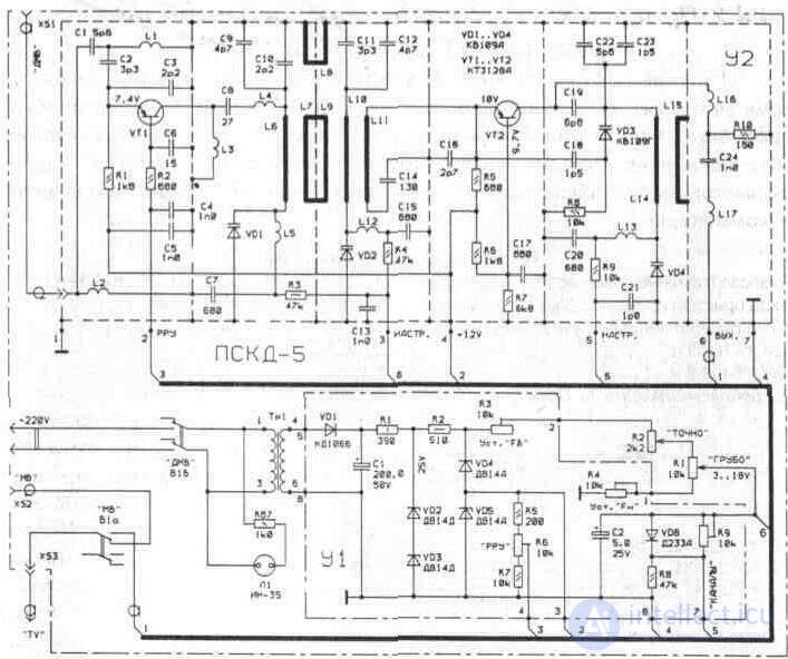
Fig. 4. 47. Schematic diagram of the PSD-5-1 block The U1 stabilization block contains a half-wave rectifier for VD1, power filter C1, two parametric stabilizers R1, VD2, VD3 (25 ± 2V), and R2, VD4, VD5 (20 ± 2V) . The converter supply voltage (10V) is applied to pin 4 from the connection point of the Zener diodes VD4 and VD5. The voltage divider R5, R6, R7 (contact 4 U1) is removed voltage for manual adjustment of the gain "RDU". The reception range of FB and FH is set by adjusting the voltage with resistors R3, R4. The voltage of the exact (R2) and coarse (R1) settings is applied to pin 3 (Un) of the converter from pin 6 of the stabilization unit. By changing the voltage on pin 5, the converter output is adjusted to the 1st (2nd) TV channel. From the divider R8, R9 (U1), the contact 5 of the converter is energized for tuning the local oscillator frequency. When translating the resistor R9 to the extreme right position, the voltage on the varicap VD4 decreases, while the capacitance of the varicap increases, which leads to a decrease in the frequency of the local oscillator and the conversion of received channels to the second TV channel. When translating the resistor R9 to the extreme left position, the received UHF channels are converted to the first television channel.
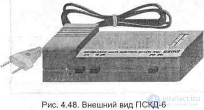
4.4.3. Prefix - channel selector decimeter range PSKD-6 (PSKD-6M)
The prefix is designed to work with television receivers meter range of any type and class without additional rework. Structurally, the prefix is made in the form of a functionally complete structure, inside which are located the mains transformer, the stabilization unit A2, the radio section A1, the controls and switching.
Specifications
Frequency range ............................................ 470 .. 640 MHz (channels 21-41)
Prefix input, (Rin = 75 Ohms) ......................................... ..... asymmetrical
Voltage transmission ratio, dB
at f = 470 MHz ............................................. .......................... ABOUT
at f = 640 MHz ............................................. ......................... + 6
Power consumption, W, not more than ................................ 5

The radio block (converter) A1 contains two stages - a radio frequency amplifier (RF amplifier) VT1 and a converter VT2, made on high-frequency transistors KT346A (Fig. 4. 49). The television signal through the connector XS1 (input UHF) is fed to the input circuit
converter. The input circuit is made in the form of a high-pass filter L1C1L2C2, which provides suppression of signals with frequencies located below the UHF range. Capacitor C4 is used to partially compensate for the reactive component of the input resistance of the transistor VT1 and improve the matching. RF amplifier is made according to the scheme with a common base, which allows to ensure good coordination with the characteristic impedance of the antenna cable (75 Ohm) in the entire frequency band. The collector circuit of the transistor is loaded with a double-circuit bandpass filter consisting of half-wave coaxial lines L6 and L10, shortened by C8, C 10, C 12, C 14 capacitors at one end of the line and the varicaps capacitors VD1, VD2 - at the other.
PF tuning over the frequency range is performed by varying the bias voltage on the varicaps VD1, VD2, which comes from pin 3 of connector XS3 through R3, R4. The setting elements in the lower end of the range are short-circuited connection loops L5, L8, and in the upper end - inductances L4, L12. The connection between the circuits of the bandpass filter is provided by the loops of the connection L7, L9. The gain is adjusted by changing the voltage of the switchgear switchgear coming from pin 1 of the XS3 connector


Fig. 4. 50. Schematic diagram of the power supply and control unit PSKD-6M
to VT1 base through R2 junction resistor. The frequency converter is made according to the scheme with OB on the transistor VT2. The connection to the RF AMP filter is provided by the L11 loop of the connection. The collector circuit of the converter through the capacitor C22 is loaded with a heterodyne circuit in the form of a half-wave line L15 (shortened by capacitors C24, C21 and the capacitance of the varicap VD3, which is used for tuning the circuit over the frequency range) and band-pass filter C25P7.
The inductance of L16 is used for decoupling at high frequency between the local oscillator circuit and the bandpass filter. Short-loop loop L14 is used to adjust the frequency of the local oscillator on the lower channels UHF, and L13 - on the top. The capacitance C18 and the capacity of the varicap VD4 provide the required amount of feedback during range tuning. The varicap voltage VD3, VD4 comes from pin 4 of connector XS3 through resistor R9.
Temperature stabilization of the frequency of heterodine depends on the TKE of the capacitors C18, C21, C24 and the stability of the parameters VD4. As a result of the beating between the frequency of the received signal and the frequency of the local oscillator at the output of the C25L17 filter, the converted signals of the carrier frequency of the image and sound of the first TV channel are formed. The converted signal from pin 5 of connector XS3 is fed to block A2. Mains voltage from switch SA2. 1 is fed to a step-down transformer TV1, with the switch SA2. 2 switches the output signal of the converter (pin 5 ХР2) through the antenna plug XW1 to the input of the TV.
Для получения напряжения питания применена схема с удвоением напряжения на элементах VD1, VD2, С1, С2, R1. На элементах VT1, R3, R6, R8, VD3, VD5 выполнен параметрический стабилизатор, к которому подключен делитель напряжения RP2, RP3, RP4, RP5. Регулировкой RP2 (Fв), RP3 (Fн) устанавливают верхнюю и нижнюю границы приема каналов, а настройкой RP4, RP5 — канал приема. Переключатель SA1 (ДМВ1-ДМВ2) осуществляет выбор предварительно настроенного ТВ канала. Напряжение питания (12В) конвертера снимается с параметрического стабилизатора VD4 R4. Напряжение ручной регулировки усиления «РРУ» устанавливается резистором RP1. Емкости С2, С4 - фильтрующие. Контроль включения питания блока ПСКД-6 осуществляет светодиодный индикатор НП.
4.4.3. Приставка - селектор каналов дециметрового диапазона ПСКД-6 (ПСКД-6М)
Приставка предназначена для работы с телевизионными приемниками метрового диапазона любого типа и класса без дополнительной их переделки. Конструктивно приставка выполнена в виде функционально законченной конструкции, внутри которой расположены сетевой трансформатор, блок стабилизации А2, блок радиотракта А1, органы управления и коммутации.
Технические характеристики
Диапазон принимаемых частот............................................ 470... 640 МГц (каналы 21-41)
Вход приставки, (Rвх = 75 Ом).............................................. несимметричный
Коэффициент передачи по напряжению, дБ
на f =470 МГц....................................................................... О
на f= 640 МГц......................................................................+ 6
Потребляемая мощность, Вт, не более................................ 5
Блок радиотракта (конвертер) А1 содержит два каскада — усилитель радиочастоты (УРЧ) VT1 и преобразователь VT2, выполненные на высокочастотных транзисторах КТ346А (рис. 4. 49). Телевизионный сигнал через разъем XS1 (вход ДМВ) поступает на входную цепь
конвертера. Входная цепь выполнена в виде фильтра верхних частот L1C1L2C2, который обеспечивает подавление сигналов с частотами, расположенными ниже диапазона ДМВ. Конденсатор С4 служит для частичной компенсации реактивной составляющей входного сопротивления транзистора VT1 и улучшения согласования. УРЧ выполнен по схеме с общей базой, что позволяет обеспечить хорошее согласование с волновым сопротивлением антенного кабеля (75 Ом) во всей полосе рабочих частот. Коллекторная цепь транзистора нагружена двухконтурным полосовым фильтром, состоящим из полуволновых коаксиальных линий L6 и L10, укороченных емкостями С8, С 10, С 12, С 14 на одном конце линии и емкостями варикапов VD1, VD2 — на другом.
Перестройка ПФ по диапазону частот осуществляется изменением напряжения смещения на варикапах VD1, VD2, которое поступает с контакта 3 разъема XS3 через R3, R4. Элементами настройки в нижнем конце диапазона служат короткозамкнутые петли связи L5, L8, а в верхнем конце - индуктивности L4, L12. Связь между контурами полосового фильтра осуществляется петлями связи L7, L9. Регулировка усиления производится путем изменения напряжения «РРУ», поступающего с контакта 1 разъема XS3
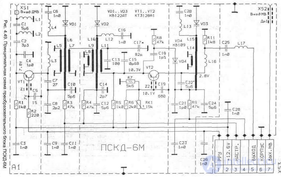
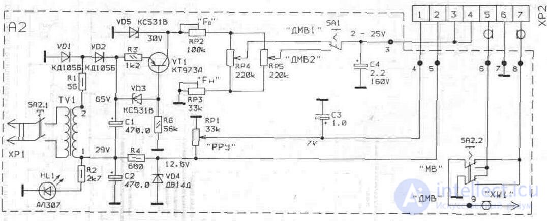
Fig. 4. 50. Принципиальная схема блока питания и управления ПСКД-6М
4. 4. 4. Приставка - селектор каналов дециметрового диапазона ПСКД-7 (ПСКД-7-1)
Технические характеристики
Диапазон принимаемых частот,
для ПСКД-7-1.............................................................................. 470... 640 МГц
для ПСКД-7 ................................................................................. 470...790 МГц
Вход приставки, (Рю = 75 Ом)....................................................................... несимметричный
Коэффициент передачи по напряжению ....................................................... 0... 10 дБ
Потребляемая мощность, Вт, не более......................................................... 5
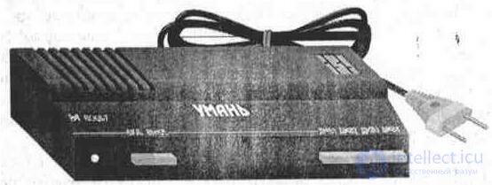
Fig. 4. 51. Внешний вид ПСКД-7 (ПСКД-7-1)
Схемотехническое построение блока А1 приставки «Умань» подобно ПСКД-6. 1, различие заключается в блоке стабилизации А2 (рис. 4. 526).
В данной приставке применено четыре переключателя S2. 1 - S2. 4 и четыре резистора настройки R9 - R 12 (выведенные на заднюю панель приставки), позволяющие произвести предварительную настройку на четыре телевизионных канала в диапазоне ДМВ.
4. 5. Активный фильтр сложения телевизионных сигналов АФС-1-12-2
Активный фильтр сложения АФС-1-12-2 предназначен для сложения и усиления телевизионных сигналов от четырех телевизионных антенн MB диапазона. Выход фильтра рассчитан на подключение двух телевизионных приемников. Устанавливать фильтр желательно как можно ближе к антеннам, например, в чердачном помещении. Фильтр необходимо защитить от прямого попадания влаги и пыли.
Main technical characteristics
Коэффициент усиления, дБ, не менее
на 1 -2 каналах.............................................................. 3,5
на 3- 5 каналах ............................................................. 4,5
на 6-12 каналах .............................................................. 4,5
Неравномерность АЧХ в полосе каждого из усиливаемых
диапазонов частот, дБ, не более ............................................................................... 3
Коэффициент отражения, дБ, не более .................................................................... 0,4
Коэффициент шума, дБ, не более ............................................................................. 9
Ток потребления, мА, не более .............................................................. 30
Напряжение источника питания, В........................................................................... 12±1, 2
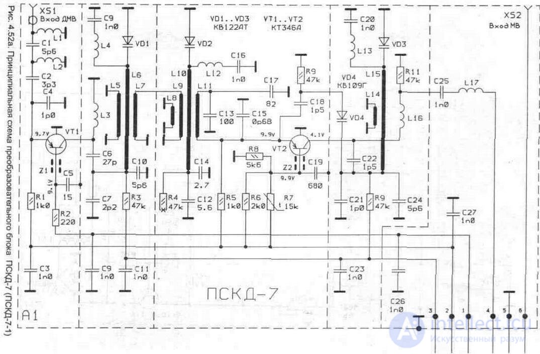
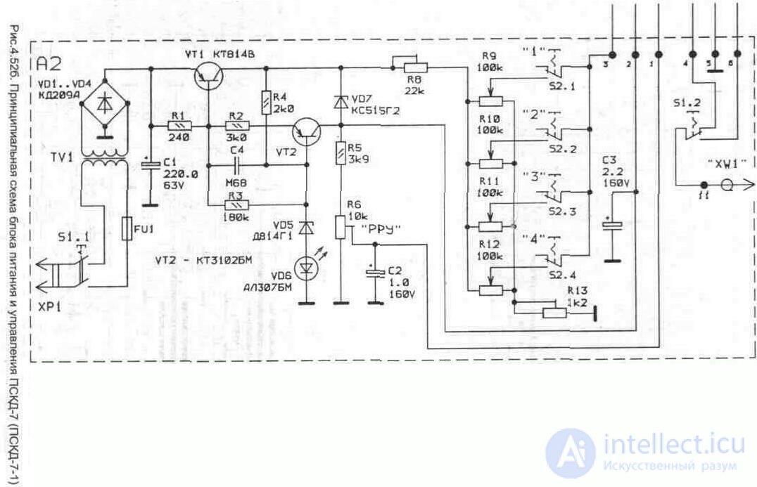
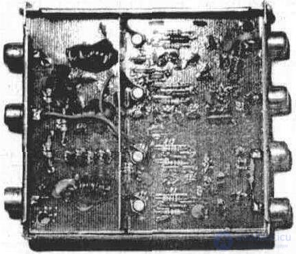
Fig. 4. 53. Внешний вид АФС-1-12-2
Конструктивно фильтр размещен в металлическом корпусе, закрываемом двумя крышками (корпус блока СКВ-1). Фильтр сохраняет работоспособность при понижении напряжения питания до 9В, но при этом ухудшаются его параметры. С одной стороны корпуса расположены входы антенн (четыре антенных гнезда) с противоположной стороны — три антенных гнезда (два выхода усиленного сигнала и вход питания).
На входе 1 - 2 ТВ канала (рис. 4. 54) установлен полосовой фильтр L1С1 C2L2C3C4C5L3. Сигнал с выхода полосового фильтра через емкость С6 поступает на усилитель 1 - 2 ТВ канала — транзистор VT1, выполненный по схеме с общей базой. Усиленный сигнал с коллекторной нагрузки VT1 (контуры L4C9, L5C10) через С11, L11 поступает на пассивный делитель телевизионного сигнала — элементы R14, R15, R16. По аналогичной схеме выполнен каскад для 3 - 5 ТВ канала: полосовой фильтр C12L6C13L7C14C15L8, усилительный элемент VT2 и нагрузка — контуры L9C19, L10С20. Сигнал через С21, L11 также поступает на пассивный делитель. Сигнал от одной из антенн (6 - 12 ТВ каналы) поступает на полосовой фильтр L14C24C25C26L15C27 через L12, а от другой антенны — через L13. Усилитель 6 - 12 ТВ канала выполнен по двухкаскадной схеме на транзисторах VT3 — по схеме с общим эмиттером, VT4 — по схеме с общей базой. Нагрузкой усилителя являются контуры L17C32, L18CЗЗ, L19C35. Усиленный сигнал 6 - 12 ТВ канала через С34 поступает на пассивный делитель. Питание на фильтр подается через VD1, предохраняющий схему от неправильного включения полярности питания.
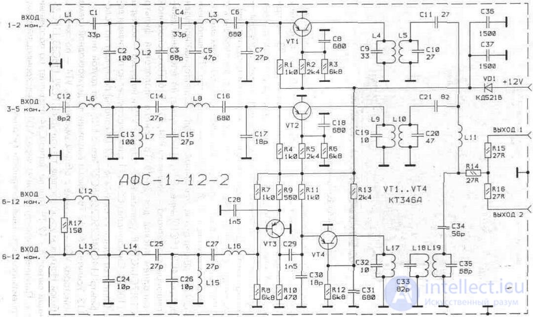 Fig.4.54. Schematic diagram of the ASF-1-12-2

Comments
To leave a comment
Television and antennas. Theory. Broadcast and cable. Digital and analog
Terms: Television and antennas. Theory. Broadcast and cable. Digital and analog