Lecture
According to GOST [3. 1], the symbol of domestic antennas begins with the letters:
AT - television antenna;
THIRD LETTER specifies the assignment of the antenna (K - collective,
And - individual);
THE FOURTH LETTER indicates the execution (D - for the horizontal polarization of the signal, G / V - the combined version, D (V) - the alternative version);
FIRST DIGITAL after letters indicates the type of antenna, which is divided depending on the number of TV channels received or frequency bands (1 - single-channel antennas operating in the frequency band of one TV channel located in the l, lI or III frequency range;
2 - multi-channel antennas operating in the frequency bands of two or more channels; 3 - broadband antennas operating in the I and II frequency range; 4 - broadband antennas operating in frequency range III; 5 - broadband antennas operating in the IV and V frequency range; 6 - broadband antennas operating in the I-III frequency bands; 7 - broadband antennas operating in all bands).
SECOND NUMBER denotes the category of reception conditions (1 is the easiest, 2 is the average degree of difficulty, 3 is the most difficult);
THIRD NUMBER denotes the number of the frequency channel in which the antenna operates;
FOURTH NUMBER indicates the ordinal number of the development.
3. 3. 1. Domestic production antennas
Many businesses produce television antennas for individual and collective use. Individual antennas are installed in the house and connected to one or more TVs. Collective antennas are used for systems for the collective reception of television programs. The signal received from one or several antennas, after distribution (if necessary and amplification), is used by a large number of subscribers.
Widespread television individual outdoor antennas "WAVE CHANNEL".
"SIGNAL-1 (2 - 5)" ATIG (B) -1.1.1.15 - ATIG (B) -1. 1. 5. 15
Outdoor television reception antennas for individual use are intended for receiving one of the television channels transmitted with horizontal (vertical) polarization in the zone of reliable reception of television signals.
Fig. 3. 20. General view of the ATIG (V) antennas 1. 1. 1. 15-1. 1. 5. 15
Technical parameters of antennas ATIG (B) 1. 1. 1. 15-1. 1. 5. 15
Reception channels ATIG (B) -1. 1. 1. 15 ............................................. ........................ one
ATIG (B) -1. 1. 2. 15 ............................................. ........................ 2
ATIG (B) -1. 1. 3. 15 ............................................. ........................ 3
ATIG (B) -1. 1. 4. 15 ............................................. ........................ four
ATMG (B) -1. 1. 5. 15 ............................................. ........................ five
Gain, dB, not less ........................................... ....................... four
KZD, dB, no more ............................................ ..........eight
KVA, measured at the end of the cable drop, not less ................................... 0, 5
Table 3. 1. Overall dimensions of ATIG antennas 1. 1. 1. 15-1. 1. 5. 15
Antenna designation | Dimensions | mm | ||||
BUT | B | AT | but | b | L | |
ATIG (V) - 1.1.1.15 | 3020 | 2690 | 2350 | 900 | 600 | 1500 |
ATIG (V) - 1.1.2.15 | 2560 | 2275 | 1990 | 765 | 510 | 1275 |
ATMG (V) - 1.1.3.15 | 1980 | 1765 | 1540 | 605 | 395 | 1000 |
ATIG (V) - 1.1.4.15 | 1800 | 1605 | 1400 | 535 | 355 | 890 |
"SIGNAL-6" ATIG (V) -4.1. 6-12.15
An outdoor television reception antenna for individual use is intended for receiving television signals transmitted with horizontal (vertical) polarization in the 174-230 MHz frequency band (channels 6 to 12) in the coverage area.
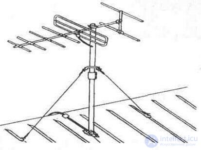
Fig. 3. 21. General view of the antenna "SIGNAL-6"
Technical parameters of antennas "SIGNAL-6"
Reception Channels ................................................ .................................................. .......... 6-12
The antenna gain with respect to the half-wave vibrator,
dB, not less .............................................. .................................................. ............... 6
KBV measured at the end of the cable drop, no less ....................................... .. 0, 6
Protective action coefficient (DPC), dB, not more than ....................................... .... -9
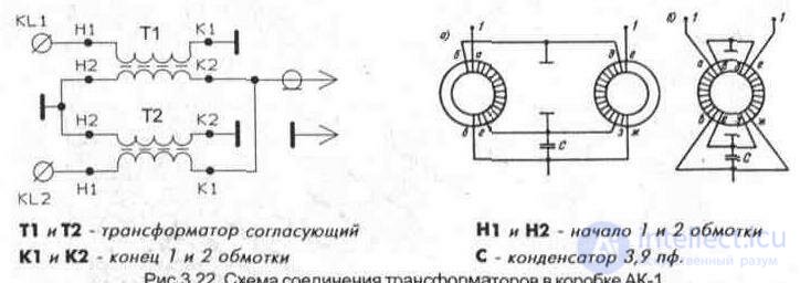
To connect the coaxial cable to the symmetrical loop vibrator of the antennas discussed above and match it, antenna boxes AK-1 or AK-2 are used, which contain an add-on filter for television channels I-II and III of meter range.
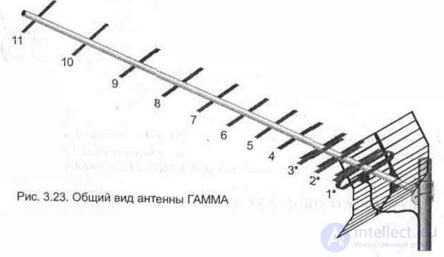
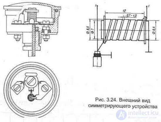
"GAMMA" ATIG (B) -5.2.21-41.19
An outdoor television reception antenna for individual use is intended for receiving television signals transmitted from the horizontal (vertical) polarization in the frequency band 470 ... 638 MHz (channels 21 to 41) in the coverage area (Fig. 3. 23).
Technical specifications
Antenna gain with respect to a half-wave vibrator, dB, not less:
470 ... 500MHZ ............................................. .................................................. ............... 9
500 ... 540MHZ ............................................. .................................................. ............... ten
540 ... 570 MHz ............................................ .................................................. ................ eleven
570 ... 638MHZ ............................................. .................................................. ............... 9, 5
Coefficient of traveling wave (KBV), measured at the end of the descent cable, no less .................................. .................................................. ................................. 0, 6
The drop cable is connected to a loop vibrator using a balancing device made in the form of the equivalent of a half-wave cable loop (Fig. 3. 24) placed in the housing of the PAK-D cable connector.
Table 3. 2. Dimensions of the ATIG (B) antenna directors 5. 2 21-41. nineteen
Ordinal | |||||||||||
number | one* | 2 * | W * | four | five | 6 | 7 | eight | 9 | ten | eleven |
directors | |||||||||||
Length mm | 221 | 218 | 214 | 211 | 207 | 203 | 200 | 196 | 192 | 188 | 185 |
“WAVE 1” (ITA-12 M) ATIG (V) - 6.1.1-12.109.
An outdoor television reception antenna for individual use is intended for receiving television signals transmitted with horizontal (vertical) polarization in the 48 5-230 MHz frequency band (channels 1 through 12) in the coverage area. The same antenna can be used to receive broadcasting signals in the UHF band 66 ... 73 MHz or 88 ... 108 MHz.
Technical parameters of WAVE-1 antennas (ITA-12M)
Reception Channels ................................................ .................................................. .......... 1-12
Gain with respect to the half-wave vibrator,
dB, not less .............................................. .................................................. .............. 2
KBV measured at the end of the cable drop no less, ........................................ .. 0, 5 ... 0, 7
Protective action coefficient (DPC), dB, not more than ....................................... .... - (10 ... 14)
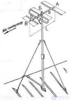
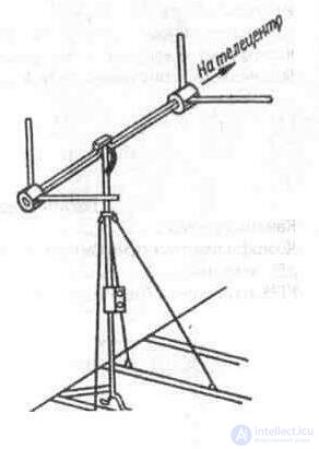
When installing the antenna of this design should pay attention to its orientation. Some viewers mistakenly believe that the shape of the antenna in the form of an arrow indicates the direction to the telecentre. The antenna should be oriented as shown in Fig. 3. 25.
Fig. 3. 25. General view of the antenna "WAVE-1"
"TAI-12" (TAI-12M). Fan vibrator.
An outdoor television reception antenna for individual use is intended for receiving television signals transmitted with horizontal (vertical) polarization in the 48, 5 ... 230 MHz frequency band (channels 1 to 12) in the coverage area. The same antenna can be used to receive broadcasting signals in the UHF band 66 ... 73 MHz or 88 ... 108 MHz. The required radiation pattern in the range of 174 ... 230 MHz (6 ... 12 channels) is formed due to the arrangement of the vibrator arms at an angle of 120 °. The angle of the solution of each fan of the shoulder is 38 °. The radiation pattern is similar to the half-wave
Fig. 3. 26. General view of the antenna TAI-12 (TAI-12M)
A new vibrator (the directional properties of this antenna in the 174 ... 230 MHz frequency range are slightly better).
Technical parameters of TAI-12 antennas (TAI-12 M)
Reception Channels ................................................ .................................................. .......... 1-12
Gain with respect to a half-wave vibrator, dB, at least in the frequency band 48, 5 ... 100 MHz ........................... .................................................. ..... ABOUT
in the frequency band 178 ... 230 MHz ......................................... .......................................... 15
KBV measured at the end of the cable drop, no less ....................................... .. 0, 4 ... 0, 7
Protective action coefficient (DPC), dB, not more than ....................................... .... - (8 ... 10)
Antenna input impedance, Ohm ............................................. ........................... 90
"LUCH-1"
Technical parameters of the LUCH-1 antennas
Reception Channels ................................................ .................................................. .......... 1-12
Antenna gain, relative to a half-wave vibrator,
dB, not less .............................................. .................................................. ............... ABOUT
KBV measured at the end of the cable drop, no less ....................................... .. 0, 5
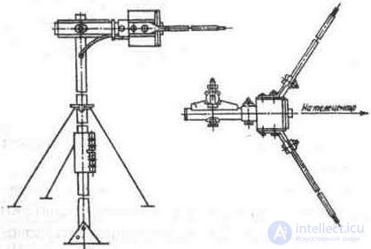
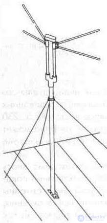
Fig. 3. 27. General view of the LUCH-1 antenna
An outdoor television reception antenna for individual use is intended for receiving television signals transmitted with horizontal (vertical) polarization in the 48, 5 ... 230 MHz frequency band (channels 1 to 12) in the coverage area. The same antenna can be used to receive broadcasting signals in the UHF band 66 ... 73 MHz or 88 .. 108 MHz.
When choosing an outdoor television antenna, it is necessary to know the parameters of the antenna, by which it is possible to determine its quality indicators (Section 3. 1) and features of reception at the antenna installation site (Section 2). It should be borne in mind that the individual and collective antennas described above are recommended for use in line of sight, so
as they do not have sufficient gain for areas with difficult reception conditions. To increase the gain of the receiving television antenna, you have available, you can add an antenna amplifier, or use an active television antenna, having in its composition a regular (antenna-mounted) antenna amplifier.
3. 3. 2. Antennas of foreign firms
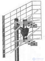
The variety of types and designs of receiving television aerials of foreign production is represented in the markets of the CIS countries. The most popular are broadband antennas with an amplifier, the supply voltage to which is fed through a descending feeder. Although they are called "active" (when equipped with a plate antenna amplifier connected directly to the antenna terminals), but according to [3. 2] these antennas are divided into passive and active elements. Therefore, it is more accurate to call them television antenna with an amplifier. Such antennas include an antenna with a grid screen. The antenna is formed by the connection of two ASP-4A or four ASP-8A (CX-8A) active wave vibrators, made in the form of a double V-shaped vibrator.
Technical parameters of the 2nd dipole antenna ASP-4A
Reception Channels ................................................ .. 6-12 ............... 21 -60
Amplification, dB ............................................... ...... 3, 5 ... 6 .............. 7 ... 10, 5
KZD, dB ................................................... .............. -16 ................... -25
Angle:
in horizontal plane ............................. 46 °
in a vertical plane ................................ 27 °
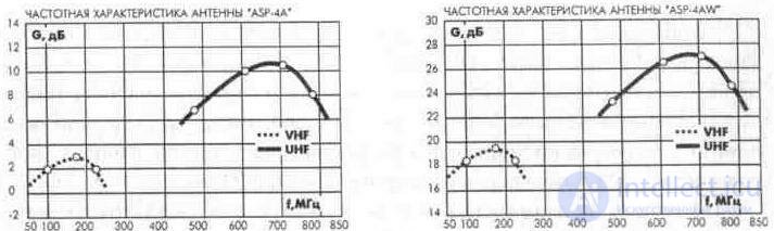
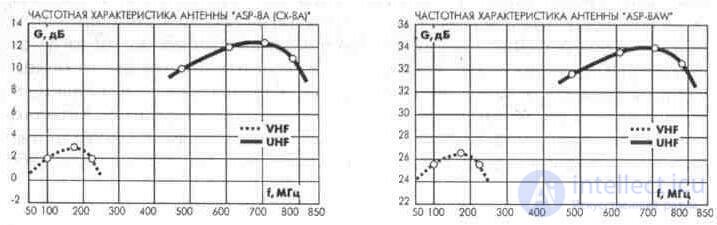
The gain of antennas with an ASP-4WA and ASP-8WA (CX-8A) amplifier is 20 ... 48 dB, depending on the type of amplifier.
The input impedance of these antennas is 240 ... 300 ohms, therefore, to match the impedance of the antenna and the feeder reduction, you must use antenna antenna SYM-01 (300/7 5) (Fig. 3.28.) Or SAI-V.
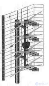
Technical parameters of the 4th ASP-8A (CX-8A) dipole antennas
Reception Channels ................................................ .. 6-12 ............... 21-60
Amplification, dB ............................................... ...... 6. 5 ... 9 .............. 10 ... 13. 5
KZD, dB ................................................... .............. -16 ................... -25
Angle:
in the horizontal plane ...................... ....... 46 °
in a vertical plane ................................ 27 °
Technical data for a specific antenna manufacturers indicate in the accompanying documentation.
Figure 3. 28. SYM-01 (300/75) antenna terminator

The maximum antenna gain falls on the upper frequencies of the decimeter range, which is due to the geometric dimensions of the active vibrators and the distance between them. If necessary, by selecting an amplifier with an appropriate characteristic, you can increase the gain on a particular channel or group of channels, using the recommendations in Section. 3. 4 of this chapter.
Along with traditional antennas of this type, atypical structures are found in which the size of the upper vibrator or the upper and lower (Fig. 3.29) is increased to expand the reception band, however, the antenna parameters mismatch. When installing the antenna should pay attention to the installation of the communication line connecting the active vibrators.
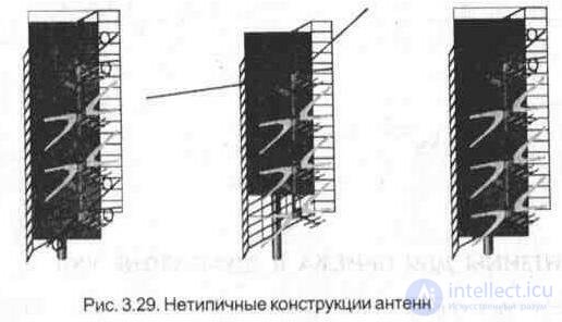
The distance between the axes of these conductors should be strictly the same along the entire length of the line (described in more detail in the sixth chapter), that:
also affects antenna matching.
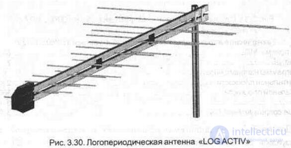
Good range properties have a log-periodic antenna (Fig. 3. 30), which has a more uniform gain over the range compared to previous antennas.
Technical parameters of the log-periodic antenna "LOG ACTIV"
Reception Channels ................................................ .................................................. .......... 1 -65
Gain, dB ............................................... ........................... 9 ... 12
KZD, dB ....................................................... .................................................. ...................... -25
SWR ................................................. .................................................. ........................... 18
Output impedance, Ohm .............................................. ...................................... 75
The gain of the antenna with the LOG ACTIV amplifier is 26 ... 46 dB, depending on the type of amplifier.
In the markets of the CIS countries are widely represented antenna "wave channel". Abroad, these antennas are called "Uda-Yagi". With minor distances from the television center, antennas of this type can be used with the number of elements from three to seven. Multi-element antennas "wave channel" is used at significant distances from the television center, as well as under difficult reception conditions, where the use of individual domestic-made antennas is ineffective.
ANTENNAS FOR RECEPTION IN THE VHF RANGE.
Single-element antennas belong to low-directional antennas and are used to receive television programs in direct line of sight and VHF broadcasting. Structurally, it is the active element of the antenna "wave channel" - loop vibrator. The radiation pattern of such an antenna in the horizontal plane looks like a figure eight, and in the vertical it looks like a circle. Since such an antenna receives a signal from both the front and rear directions with the same magnitude (CPD = 0), high structures and other objects that are sources of television signal re-reflection should not be located near the antenna. Therefore, the use of such antennas is desirable for receiving VHF FM broadcasting.
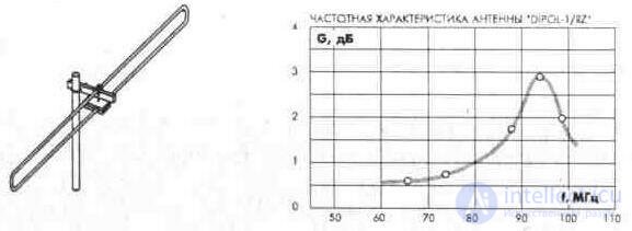
Fig. 3. 31. Single-element antenna for receiving VHF "DIPOL 1 / RZ"
Technical parameters of 1-element antenna "DIPOL 1 / RZ"
Reception frequency, MHz .............................................. .................................................. .. 88 ... 108
Gain, dB ............................................... .................................................. .............. 2
Angle:
in the horizontal plane ............................................... ....................................... 2x80 °
in a vertical plane ............................................... 360 °
KZD, dB ....................................................... .................................................. ...................... 0
Output impedance. Ohm ................................................. ................................... 300
For the approximation of the radiation pattern in the horizontal plane to a circular loop vibrator is bent in the shape of a circle (Fig. 3. 32).
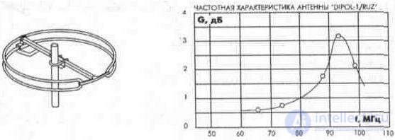
Fig. 3. 32. Single-element antenna for receiving VHF "DIPOL 1 / RUZ"
Technical parameters of the 1-DIPOL 1 / RUZ 1-antenna
Reception frequency, MHz .............................................. .................................................. .. 88 ... 108
Gain, dB ............................................... .................................................. ............. 2
Angle:
in the horizontal plane ............................................... ........................................ 2x 80 °
in a vertical plane ............................................... ........................................... 360 °
KZD. dB ................................................. .................................................. .................... 0
Output impedance, Ohm .............................................. ...................................... 300
To raise the level of gain in these antennas, a plate amplifier is used.
ANTENNAS FOR RECEPTION IN THE RANGE OF METER WAVES (VHF).
To receive television programs in this wavelength band, antennas with the number of elements from two to eleven are used. With an increase in the number of elements, the gain increases, and the geometric dimensions of the antenna in this wavelength range significantly increase. Antennas have good directivity and low side and rear lobes.
The appearance of antennas for reception in the range of meter waves is shown in Fig. 3. 33.
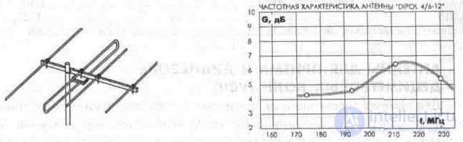
Fig. 3. 33. DIP antennas 4 / 6-12.
Technical parameters of the 4-element antenna "DIPOL 4 / 6-12":
Reception Channels ................................................ .............................. 6-12
Gain. dB ................................................. ................................. 4 .. 7
Angle:
in the horizontal plane ............................................... ........................... 49 °
in a vertical plane ............................................... ...................... b0 °
SWR ................................................. .................................................. ........................... 1.4 ... 2.1
KZD, dB ....................................................... .................................................. ...................... eight
Output impedance, Ohm .............................................. .................................... 300
Технические параметры 7-элементной антенны «DIPOL 7/6-12»:
Каналы приема................................................................................. б- 12
Усиление. дБ..................................................................... R я
Угол диаграммы направленности:
в горизонтальной плоскости................................................................................ 45°
в вертикальной плоскости.......................................................................... 58°
КСВ............................................................................................. 1, 3... 1, 97
КЗД, дБ...................................................................................................................... 12
Выходное сопротивление, Ом.................................................................................. 300
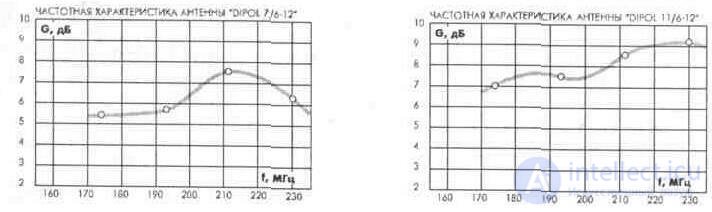
Технические параметры «-элементной антенны «DIPOL 11/6-12»:
Каналы приема.................................................................. 6-12
Усиление.дБ.........................................................................................7.. 9,2
Угол диаграммы направленности:
в горизонтальной плоскости .......................................................... 31°
в вертикальной плоскости ............................................................................... 48°
КСВ ......................................................................................................... 1, 48.. 1,76
КЗД, дБ ...........................................................................................................-13,5
Выходное сопротивление, Ом ....................................................................... 300
АНТЕННЫ ДЛЯ ПРИЕМА В ДИАПАЗОНЕ ДЕЦИМЕТРОВЫХ ВОЛН (УВЧ)
Для приема телевизионных программ в этом диапазоне волн применяют многоэлементные антенны с большим коэффициентом усиления. Такие антенны обладают острой направленностью и незначительным уровнем боковых и задних лепестков. Внешний вид антенн для приема в диапазоне дециметровых волн приведен на рис. 3. 34... 3. 36.
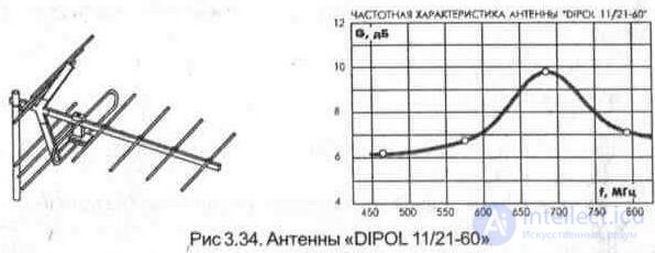
Технические параметры 11-элементной антенны «DIPOL 11/21-60»:
Каналы приема........................................................................................................... 21 -60
Усиление, дБ.............................................................................................................. 5, 5... 9
Угол диаграммы направленности:
в горизонтальной плоскости...................................................................................... 32°
в вертикальной плоскости......................................................................................... 49°
КСВ............................................................................................................................. 1. 48... 1. 81
КЗД. дБ...................................................................................................................... - (19... 26)
Выходное сопротивление. Ом................................................................................... 300
Технические параметры 19-элементной антенны «DIPOL 19/21-60»:
Каналы приема............................................................................................................ 21 -60
Amplification, dB ............................................... .................................................. .............. eleven
Angle:
in the horizontal plane ............................................... ........................................ 23 °
in a vertical plane ............................................... ...................................... 42 °
SWR ................................................. .................................................. ........................... 1.28..1.7
KZD.dB ....................................................... .................................................. ...................... - (19 ... 26)
Output impedance, Ohm .............................................. ................................. 300
The appearance of the POLARIS 60 / 21-60 antenna is shown in fig. 3.35.
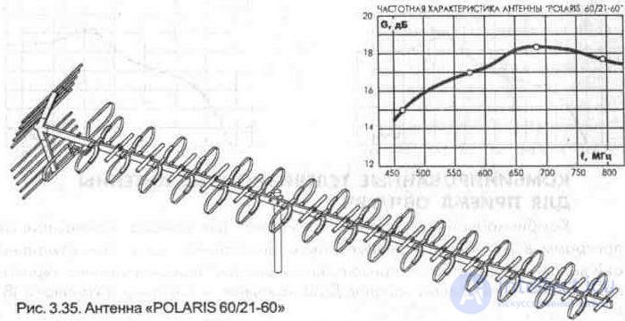
Технические параметры 60-элемвнтной антенны «POLARIS 60/21-60»
Каналы приема ............................................................................................................ 21 -60
Усиление, дБ .............................................................................................................. 16...18
КЗД.дБ ........................................................................................................................26
Выходное сопротивление, Ом.................................................................................... 75
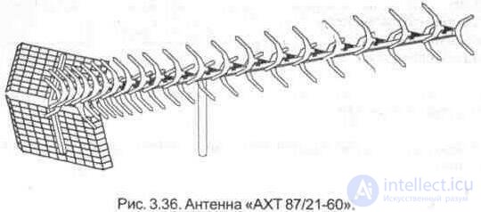
Внешний вид антенны АХТ 87/21-60 приведен на рис. З.З6.
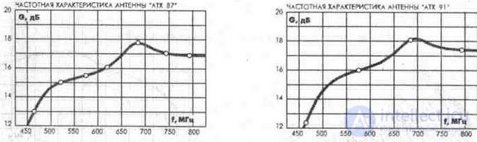
Технические параметры 87-элементной антенны «АХТ87/21-60»
Каналы приема ............................................................................................................ 21 -60
Усиление, дБ............................................................................................................... 13...17
КЗД.дБ .......................................................................................................................20
Выходное сопротивление. Ом.................................................................................... 300
Технические параметры 91-элементной антенны «АХТ 91/21-60»
Каналы приема ............................................................................................................ 21 -60
Усиление, дБ ............................................................................................................... 13...18
КЗД.дБ ........................................................................................................................20
Выходное сопротивление, Ом.................................................................................... 300
КОМБИНИРОВАННЫЕ ТЕЛЕВИЗИОННЫЕ АНТЕННЫ ДЛЯ ПРИЕМА ОВЧ/УВЧ.
Комбинированные антенны применяют для приема телевизионных программ в метровом и дециметровом диапазонах волн. Конструктивно они выполненны на общей горизонтальной стреле. Передняя антенна «волновой канал» — для приема каналов ДМВ, а задняя — для приема каналов MB.
В некоторых вариантах комбинированных антенн антенна метрового диапазона предназначена для приема волн вертикальной поляризации. Крепление таких антенн к мачте производится в центре тяжести стрелы, однако при этом рефлектор дециметровой антенны оказывает влияние на прием метровых волн. Применять комбинированные антенны желательно при незначительных удалениях от телевизионного центра и в зонах, где уровень сигнала метрового диапазона достаточно велик. Для поднятия усиления некоторые антенны укомплектованы усилителем, при этом в обозначении антенн добавлен индекс «W».
Внешний вид антенны «DIPOL 26/6-12/21-60», предназначенной для приема в диапазоне метровых и дециметровых волн приведен на рис. 3. 37.
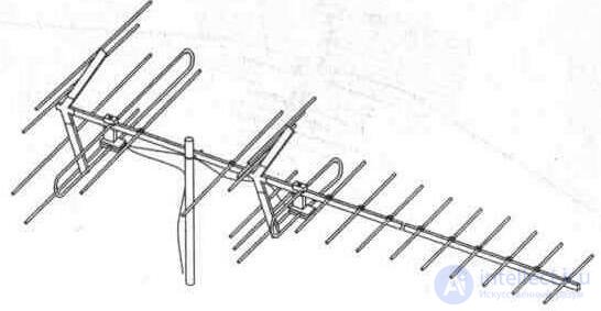
РисЗ. 37. Антенна «DIPOL 26/6-12/21-60».
Технические параметры 26-элементной антенны «DIPOL 26/6-12/21-60» Каналы приема...................................................................................................... 6 -12/21 - 60
Усиление, дБ........................................................................................................ 12/26
КЗД, дБ................................................................................................................. - (6... 8/8... 12)
Выходное сопротивление, Ом.............................................................................. 75
Технические параметры 14-эле1тентной антенны «POLARIS 14/6-12/21-60»
Каналы приема...................................................................................................... 6-12/21 -60
Усиление, дБ......................................................................................................... 2... 3/8... 11
КЗД, дБ................................................................................................................. 0/-10
Выходное сопротивление, Ом............................................................................ 75

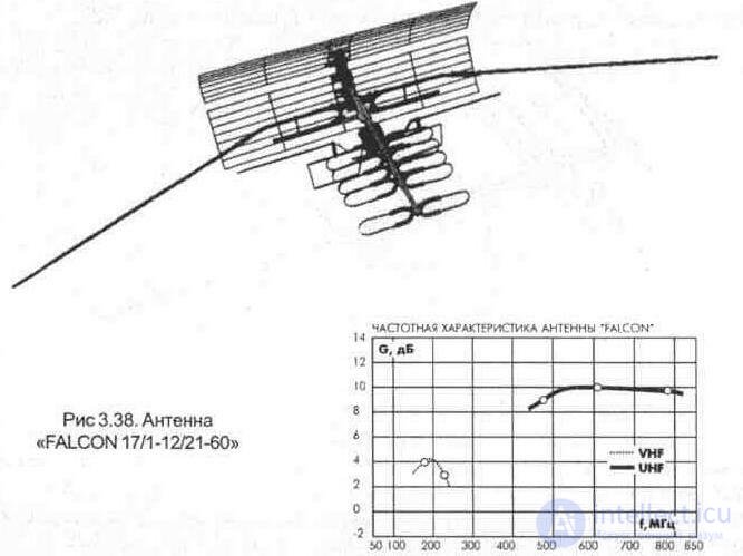
Внешний вид антенны «FALCON 17/1-12/21-60», предназначенной для приема в диапазоне метровых и дециметровых волн, приведен на рис. 3. 38.
Технические параметры 17-элвмвнтной антенны «FALCON 17/1-21/21-60»
Каналы приема...................................................................................................... 1... 12/21... 60
Усиление, дБ......................................................................................................... З... 5/8... 11
КЗД, дБ................................................................................................................. - (4/24)
Выходное сопротивление, Ом.............................................................................. 75
Наряду с индивидуальными антеннами для приема в метровом и дециметровом диапазоне волн применяются и профессиональные антенны для систем общего пользования или приема сигнала в особо сложных условиях. Эти антенны характеризуются усиленной механической конструкцией и повышенными техническими характеристиками. В названии таких антенн буквами и цифрами обозначают количество элементов и номера принимаемых каналов.
Например: ATV 5/7-8 — антенна телевизионная профессиональная, пятиэлементная, для приема 7-8 телевизионных каналов.
Более полно параметры зарубежных антенн приведены в приложении 5.
3. 3. 3. Антенна «TEVSAN 7750-A»
Комбинированная антенна «TEVSAN 7750-A» с регулируемым усилением предназначена для приема телевизионных сигналов в метровом и дециметровом диапазонах волн. В конструкции антенны предусмотрена установка усилителя в герметичном корпусе на центральной стреле. Дециметровая часть антенны - волновой канал, имеет пять пассивных элементов (директора) Х-образной формы для расширения полосы приема. Прием каналов метрового диапазона волн осуществляется петлевым вибратором изогнутой формы. Питание усилителя осуществляется по фидеру снижения
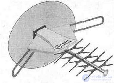
от блока питания, находящегося вблизи телевизора.
Fig. 3. 39. Внешний вид антенны «TEVSAN 7750-A» с усилителем и блоком питания
Усилитель имеет два канала усиления: канал метрового диапазона волн выполнен на транзисторе VT1, дециметрового — выполнен на транзисторах VT2, VT3 (рис. 3. 40). Все каскады усиления выполнены по схеме с общим эмиттером. Усиление антенного усилителя регулируется дистанционно с блока питания, путем изменения питающего напряжения. Индикация изменения напряжения источника питания осуществляется светодиодом НL1.
3.3.4. Антенна «NK-3202S» с усилителем
Эта антенна по конструктивному исполнению аналогична TEVSAN 7750-А. Отличие состоит в незначительном схемном решении усилителя
(рис.3.41)
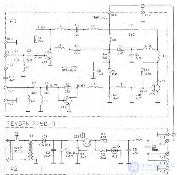
Fig. 3. 40. Принципиальная схема усилителя антенны «TEVSAN 7750-А»
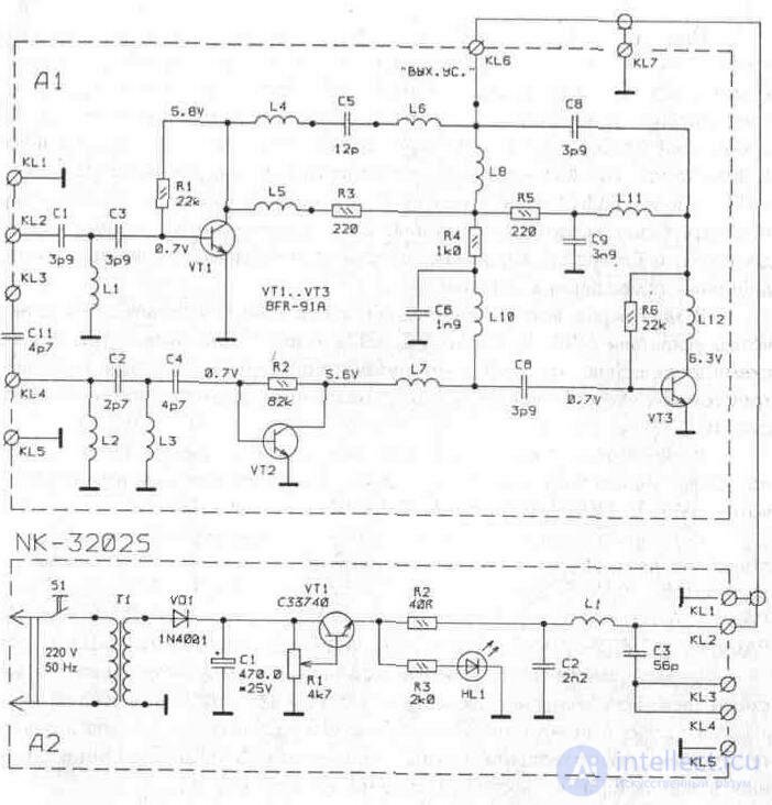
Fig. 3. 41. Принципиальная схема усилителя антенны «NK-3202S»

Comments
To leave a comment
Television and antennas. Theory. Broadcast and cable. Digital and analog
Terms: Television and antennas. Theory. Broadcast and cable. Digital and analog