Lecture
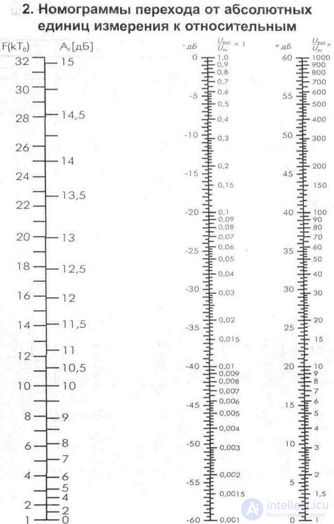
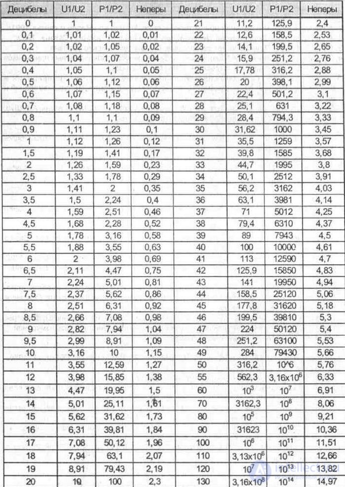
3. Tables of transition from absolute to relative units
Db | U1 / U2 | P1 / P2 | Db | U1 / U2 | P1 / P2 |
0.5 | 1,059 | 1,122 | 21 | 11.22 | 125.9 |
1.0 | 1,122 | 1,259 | 22 | 12.59 | 158.5 |
1.5 | 1,189 | 1,413 | 23 | 14,13 | 199.5 |
2.0 | 1,259 | 1,585 | 24 | 15.85 | 251.2 |
2.5 | 1,334 | 1,778 | 25 | 17.78 | 316.2 |
3.0 | 1,413 | 1,995 | 26 | 19.95 | 398.1 |
3.5 | 1,496 | 2,238 | 27 | 22.39 | 501.2 |
4.0 | 1,585 | 2.512 | 28 | 25.12 | 631 |
4.5 | 1,679 | 2,818 | 29 | 28.18 | 794.3 |
5.0 | 1,778 | 3.162 | thirty | 31.62 | 1000 |
5.5 | 1,884 | 3.55 | 31 | 35.48 | 1259 |
6.0 | 1,995 | 3,981 | 32 | 39.81 | 1585 |
6.5 | 2.113 | 4.47 | 33 | 44.67 | 1995 |
7.0 | 2,239 | 5,012 | 34 | 50.12 | 2512 |
7.5 | 2.371 | 5.62 | 35 | 56.23 | 3162 |
8.0 | 2.512 | 6.310 | 36 | 63,10 | 3981 |
8.5 | 2,661 | 7,079 | 37 | 70.79 | 5012 |
9.0 | 2,818 | 7,943 | 38 | 79.43 | 6310 |
9.5 | 2,985 | 8,913 | 39 | 89.13 | 7943 |
ten | 3.162 | 10.00 | 40 | 100.0 | 10,000 |
10.5 | 3,350 | 11.22 | 41 | 112.2 | 12589 |
eleven | 3,548 | 12.59 | 42 | 125.9 | 15849 |
11.5 | 3,758 | 14,13 | 43 | 141.3 | 19953 |
12 | 3,981 | 15.85 | 44 | 158.5 | 25119 |
12.5 | 4,217 | 17.78 | 45 | 177.8 | 31623 |
13 | 4,467 | 19.95 | 46 | 199.5 | 39811 |
13.5 | 4,732 | 22.39 | 47 | 223.9 | 50119 |
14 | 5,012 | 25.12 | 48 | 251.2 | 63096 |
14.5 | 5,309 | 28.18 | 49 | 281.8 | 79433 |
15 | 5.623 | 31.62 | 50 | 316.2 | 100,000 |
15.5 | 5,957 | 35.48 | 51 | 354.8 | 125893 |
sixteen | 6.310 | 39.81 | 52 | 398.1 | 158489 |
16.5 | 6,683 | 44.67 | 53 | 446.7 | 199526 |
17 | 7,079 | 50.12 | 54 | 501.2 | 251189 |
17.5 | 7,499 | 56.23 | 55 | 562.3 | 316228 |
18 | 7,943 | 63,10 | 56 | 631.0 | 398107 |
18.5 | 8,414 | 70.79 | 57 | 707.9 | 501187 |
nineteen | 8,913 | 79.43 | 58 | 794.3 | 630957 |
19.5 | 9,441 | 89.13 | 59 | 891.3 | 794328 |
20 | 10.00 | 100.0 | 60 | 1000.0 | 100,000 |
Db | • U1 / U2 | P1 / P2 | Db | U1 / U2 | P1 / P2 |
-0.5 | 0.944 | 0.841 | -21 | 0.089 | 0,008 |
-one | 0.891 | 0.794 | -22 | 0.079 | 0,006 |
-1.5 | 0.841 | 0.708 | -23 | 0.071 | 0,005 |
-2 | 0.794 | 0,691 | -24 | 0.063 | 0,004 |
-2.5 | 0.750 | 0.562 | -25 | 0.056 | 0,0030 |
-3 | 0.708 | 0.501 | -26 | 0.050 | 0,0025 |
-3,5 | 0.668 | 0.447 | -27 | 0.045 | 0,0020 |
-four | 0.631 | 0.398 | -28 | 0.040 | 0,0016 |
-4,5 | 0.596 | 0.355 | -29 | 0.035 | 0,0013 |
-five | 0.562 | 0.316 | -thirty | 0.032 | 0,0010 |
-5,5 | 0.531 | 0.282 | -31 | 0.028 | 0.0008 |
-6 | 0.501 | 0.251 | -32 | 0.025 | 0.0006 |
-6,5 | 0.473 | 0,224 | -33 | 0.022 | 0.0005 |
-7 | 0.447 | 0,200 | -34 | 0.020 | 0.0004 |
-7.5 | 0.421 | 0.178 | -35 | 0.018 | 0.0003 |
-eight | 0.398 | 0.158 | -36 | 0.016 | 0,00025 |
-8,5 | 0.376 | 0.141 | -37 | 0.014 | 0.0002 |
-9 | 0.355 | 0.126 | -38 | 0.013. | 0,00016 |
-9,5 | 0.335 | 0.112 | -39 | 0.011 | 0,00013 |
-ten | 0.316 | 0,100 | -40 | 0,010 | 0.0001 |
-10,5 | 0,299 | 0.089 | -41 | 0,009 | 0,00008 |
-eleven | 0.282 | 0.079 | -42 | 0,008 | 0,00006 |
-11,5 | 0.266 | 0.071 | -43 | 0,007 | 0,00005 |
-12 | 0.251 | 0.063 | -44 | 0,006 | 0,00004 |
-12,5 | 0.237 | 0.056 | -45 | 0,006 | 0,00003 |
-13 | 0,224 | 0.050 | -46 | 0,005 | 0,000025 |
-13,5 | 0.211 | 0.045 | -47 | 0,0045 | 0,00002 |
-14 | 0,200 | 0.040 | -48 | 0,004 | 0,000016 |
-14,5 | 0.188 | 0.035 | -49 | 0,0035 | 0,000013 |
-15 | 0.178 | 0.032 | -50 | 0,0032 | 0.00001 |
-15,5 | 0.168 | 0.028 | -51 | 0,0028 | 0,000008 |
-sixteen | 0.158 | 0.025 | -52 | 0,0025 | 0,000006 |
-16,5 | 0.150 | 0.022 | -53 | 0,0022 | 0,000005 |
-17 | 0.141 | 0.020 | -54 | 0,002 | 0,000004 |
-17,5 | 0.133 | 0,018 | -55 | 0,0018 | 0,000003 |
-18 | 0.126 | 0.016 | -56 | 0,0016 | 0,0000025 |
-18,5 | 0.119 | 0.014 | -57 | 0,0014 | 0,000002 |
-nineteen | 0.112 | 0.013 | -58 | 0,0013 | 0,0000016 |
-19,5 | 0.106 | 0.011 | -59 | 0,0011 | 0,0000013 |
-20 | 0,100 | 0,010 | -60 | 0.001 | 0,000001 |
4. Foreign and domestic transistors used in the described circuits of amplifiers and converters
Transistors may differ in pin assignment or housing type. The arrangement of the leads of transistors of the same type produced by different companies may not coincide (transistor BFR 96, manufactured by Siemens and Motorola). Therefore, it is necessary to use reference sheets of manufacturers, since in the reference books these differences are not given.
Code | Body structure | Name n / n | Brief Parameters |
N3 | SOT 23, Si-n | 2SC1653 | S, Nix, 150V, 0.05A, 150MHz |
P1 | SOT-23, Si-n | BFP 91A | UHF-A, 15V, 50mA, 6GHz, 0.35W |
P1 | SOT-23. Si-n | BFR 92 | UHF-A, 20V, 25mA, 5GHz |
P2 | SOT-23, Si-n | BFR 92A | UHF-A, 20V, 25mA, 5GHz |
P2 | SOT-323, Si-n | BFQ 67 | UHF-A, ha, 20V, 0.05A. 7.5GHz |
R1 | SOT-23, Si-n | BFR 93 | UHF-A, 20V, 25mA, 5GHz |
R1 | SOT-143, Si-n | BFP 196 | UHF-A, 12V, 0.1A, 8GHz |
R2 | SOT-23, Si-n | 2SC2351 | UHF-ra, 25V. 0.07 mA, 4.5GHz |
R2 | SOT-23, Si-n | BFR 93 A | UHF-A, 20V, 25mA, 5GHz |
Rh | SOT-143, Si-n | BFP 183 | UHF-A, 20V, 65mA, 8GHz |
Rh | SOT-23. Si-n | BFR 183 | UHF-A, 20V, 65mA, 8GHz |
V1 | SOT-23, Si-n | BFT25 | UHF-A, 8V, 2.5mA, 2.3GHz, 3mW |
V2 | SOT-23, Si-n | BFQ 67 | UHF-A, ra, 20V, 0.05A, 7.5GHz |
V3 | SOT-143, Si-n | BFG 67 | UHF / UHF-A, 10V, 0.05A, 7.5GHz, 0.3W, 3dB, 6dB. |
- | SOT-37, Si-n | BFR 91A | UHF-A, 8 V, 30 mA, 6 GHz, 0.3W, 1.6 dB, 14 dB. |
- | SOT-37, Si-n | BFR 96 | UHF-A, 10V, 50mA, 5GHz, 0.5 W, 3.3 dB, 16 dB. |
SOT-37, Si-n | BFR 96S | UHF-A, 10 V, 70 mA, 5 GHz, 0.7W, 4dB, 11.5dB. | |
415 | SOT-143, Si-n | AT41511 | UHF-A, 5 V, 0.9 GHz, 1.0 dB, 17.5 dB |
415 | SOT-23, Si-n | AT 41533 | UHF-A, 5 V, 0.9 GHz, 1.0 dB, 14.5 dB |
67 | SOT-143, Si-n | BFP 67 | UHF / UHF-A, 20V, 0.05A, 7.5GHz |
- | Si-n | KT639B | S, Nix, 100V, 1.5A, 20MHz, 10 W, (63 - 160) * |
4B | Si-p | KT814B | S, Nix, 60V, 1.5A, 3MHz, 10 W. (40) * |
- | Si-p | KT837K | S, Nix, 70V. 8A, 1MHz, 30 W, 5 - 17dB |
- | Si-p | KT837F | S, Nix, 60V, 7.5A, 1MHz. 30 W, 3 - 17 dB |
- | Si-p | П214В | S, Nix, 55V, 5A, 270 Hz, 10 W, (20) * |
- | Si-p | P214G | S, Nix, 60V, 7.5A, 270 Hz, 30 W, (15 ... 40) * |
- | Si-n | MP37B | 30V, 20 mA, 1MHz, 0.15 W, (25 ... 50) " |
Si-p | MP42 | 15V, 200 mA, 1MHz, 0.2 W, (20 ... 35) " | |
- | Si-p | GT313B | UHF-A, 15V, 30 mA, 100 MHz, 0.1 W, 8 dB, (15 ... 200) * |
- | KT-1-12, Si-n | GT346A | UHF-A, 20V. 10 mA, 700 MHz. 0.05 W, 7 dB, 10.5 dB |
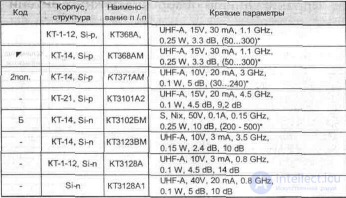
In the section of brief parameters, the following are indicated in sequence: scope, U ke (voltage between transitions), I c (collector current), Frp (limit frequency of amplification), Pk (power dissipation), F (noise figure), G (gain).
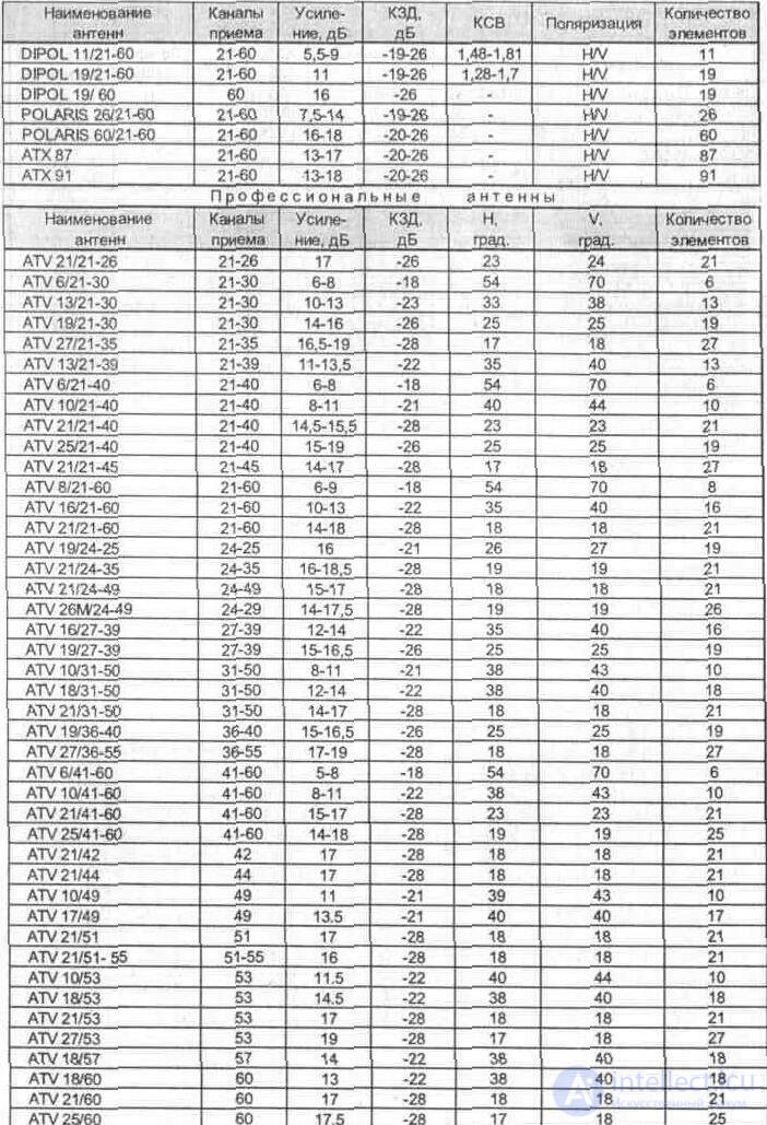
5. Comparative review of foreign antennas
RADIO ANTENNA VHF FM (UKV FM)
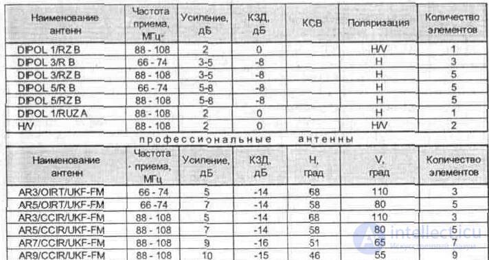
Note: H is horizontal polarization, V is vertical.
MB TELEVISION ANTENNAS (VHF)
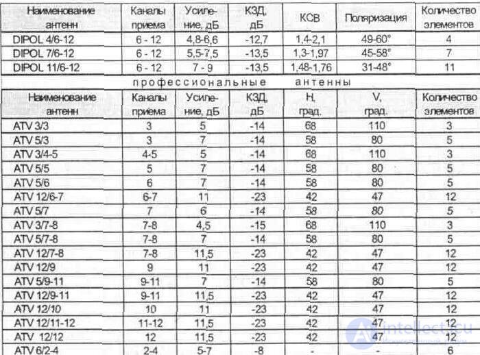
TELEVISION ANTENNA UHF
COMBINED TELEVISION ANTENNA MV / UHF (VHF / UHF)

Note: Н - horizontal polarization, V— vertical.
6. Comparative table of parameters of plate amplifiers
Amplifier type | Reception channels | f. MHz | G, dB | F.dB | Rvh / ohm, Ohm |
APS 03 | 6 - 60 | 174-790 | 12 | 1.2 * | 300/75 |
APS 07 | 6 - 60 | 174-790 | 24 | 2.6 * | 300/75 |
SWA-1 | 1 - 68 | 48,5-854 | 8 - 10 | 2.5 | 300/75 |
SWA-1 / LUX | 1 - 68 | 48,5-854 | 15-18 | 0.9 | 300/75 |
SWA-1 / S | 1 - 68 | 48,5-854 | ten | 2.3 | 300/75 |
SWA-1 / S / LUX | 1 - 68 | 48,5-854 | 16 - 18 | 0.9 | 300/75 |
SWA-UKF-01 | 60 -110 | 23 - 28 | 3.1 | 300/75 | |
SWA-2 | 1 - 68 | 48,5-854 | 23 - 28 | 3.2 | 300/75 |
WS-2 | 1 - 68 | 48,5-854 | 23 - 28 | 3.2 | 300/75 |
SWA-3 | 1 - 68 | 48,5-854 | 23 - 28 | 3.1 | 300/75 |
SWA-3 / LUX | 1 - 68 | 48,5-854 | 25 - 30 | 3.0 | 300/75 |
SWA-4 / LUX | 1 - 68 | 48,5-854 | 28 - 32 | 2.6 | 300/75 |
SWA-5 | 1 - 68 | 48,5-854 | 32 - 36 | 1.9 | 300/75 |
SWA-6 | 1 - 68 | 48,5-854 | 32 - 36 | 1.9 | 300/75 |
SWA-7 | 1 - 68 | 48,5-854 | 32 - 38 | 1.7 | 300/75 |
SWA-7 / LUX | 1 - 68 | 48,5-854 | 32 - 38 | 1.7 | 300/75 |
SWA-7 / zw | 1 - 68 | 48,5-854 | 32 - 38 | 1.7 | 300/75 |
SWA-8 | 1 - 68 | 48,5-854 | 28 - 30 | 2.9 | 300/75 |
SWA-8 / s | 1 - 68 | 48,5-854 | 28 - 30 | 2.8 | 300/75 |
SWA-8 / zw | 1 - 68 | 48,5-854 | 28 - 30 | 2.9 | 300/75 |
SWA-9 | 1 - 68 | 48,5-854 | 32 - 39 | 1.7 | 300/75 |
SWA-10 | 1 - 68 | 48,5-854 | 23 - 30 | 3.1 | 300/75 |
SWA-11 | 1 - 68 | 48,5-854 | thirty | 2.5 | 300/75 |
SWA-12 | 1 - 68 | 48,5-854 | 36 | 1.8 | 300/75 |
SWA-13 | 1 - 68 | 48,5-854 | 32 | 1.8 | 300/75 |
SWA-14 | 1 - 68 | 48,5-854 | 32 | 2.4 | 300/75 |
SWA-15 | 1 - 68 | 48,5-854 | 34 | 1.9 | 300/75 |
SWA-16 | 1 - 68 | 48,5-854 | 34 | 1.8 | 300/75 |
SWA-21 | 1 - 69 | 48.5-862 | 10 - 16 | 2.2 | 300/75 |
SWA-31 | 1 - 69 | 48.5-862 | 22 - 28 | 3.0 | 300/75 |
SWA-32 | 1 - 69 | 48.5-862 | 22 - 28 | 3.0 | 300/75 |
SWA-41 | 1 - 69 | 48.5-862 | 30 - 33 | 1.5 | 300/75 |
SWA-42 | 1 - 69 | 48.5-862 | 30 - 33 | 1.5 | 300/75 |
SWA-43 | 1 - 69 | 48.5-862 | 26 - 30 | 1.5 | 300/75 |
SWA-44 | 1 - 68 | 48,5-854 | 32 | 2.4 | 300/75 |
SWA-47 | 1 - 68 | 48,5-854 | 32 - 38 | 1.7 | 300/75 |
SWA-47 (AST) | 1 - 69 | 48,5-854 | 30 - 35 | 1,3 | 300/75 |
SWA-49 | 1 - 68 | 48,5-854 | 32 - 39 | 1.7 | 300/75 |
Amplifier type | Reception channels | f, MHz | G.dB | F, dB | Rvh / ohm, Ohm |
SWA-49 (AST) | 1 - 69 | 48.5-862 | 34 - 40 | 1.2 | 300/75 |
SWA-455 | 1 - 69 | 48.5-862 | 22 - 30 | 1.8 | 300/75 |
SWA-555 | 1 - 68 | 48,5-854 | 34 | 1.9 | 300/75 |
SWA-555 (AST] | 1 - 69 | 48.5-862 | 28-34 | 1.7 | 300/75 |
PA-2 | - | 40 - 800 | 12 | 3.5 | 300/75 |
A & S-110 | - | 40 - 800 | 12 | 3.5 | 300/75 |
PA-5 | 1 - 69 | 48.5-862 | 28-34 | 1.7 | 300/75 |
A & S-130 | 1 - 69 | 48.5-862 | 28-34 | 1.7 | 300/75 |
PA-9 | 1 - 69 | 48.5-862 | 28-34 | 1.7 | 300/75 |
A & S-140 | 1 -69 | 48.5-862 | 28-34 | 1.7 | 300/75 |
PA-10 | - | 40 - 800 | 22 | 3.9 | 300/75 |
A & S-120 | - | 40 - 800 | 22 | 3.9 | 300/75 |
Wa-031 | 6-60 | 174-790 | 22 | 3.0 | 300/75 |
Wa-032 | 6-60 | 174-790 | 24 | 2.2 | 300/75 |
Wa-041 | 6-60 | 174-790 | 32 | 1.7 | 300/75 |
Wa-042 | 6-60 | 174-790 | 32 | 1.7 | 300/75 |
Wa-501S1 | 6 - 60 | 174-790 | 32 | 1.5 | 300/75 |
Wa-501S3 | 6-60 | 174-790 | 34 | 1.6 | 300/75 |
Amplifier type | Reception channels | f.MHz | G, dB | F.dB | Pout dBmV | SWR | Rvh / ohm, Ohm |
RAE-14 | 1 -60 | 48,5-790 | 25-30 | <2.7 | 98 | 1.5 | 300/75 |
RAE-42 | 1-60 | 48,5-790 | 25 - 30 * | <2.5 | 102 | 1.8 | 300/75 |
RAE-43 | 1 -69 | 48.5-862 | 26-32 | <2.5 | 104 | 1.2 | 300/75 |
RAE-45 | 1 -69 | 48.5-862 | 24 - 28 * | <2.2 | 105 | 1.2 | 300/75 |
RAE-65 | 1 -69 | 48.5-862 | 24-28 | <2.5 | 104 | 1.2 | 300/75 |
PAE-65TS | 1 -69 | 48.5-862 | 24-28 | <1.7 | 112 | 1.6 | 300/75 |
D95 | 1-60 | 48,5-790 | 32 | <2.5 | 102 | 1.8 | 300/75 |
2000dci | 1 -69 | 40-800 | 31 | 3.5 | - | 1.8 | 300/75 |
7. The design of imported coaxial cables
Cable brand | Internal insulation | External conductor | Outer shell | |
1.5D-2V | ed | 1.5 PE | G (Cu) | 2.9 PVC |
3D-2V | ed | 3.0 PE | G (Cu) | 5.3 PVC |
50-2V | 1.4 ed | PE 5.0 | G (Cu) | 7.3 PVC |
80-2V | ed | 8.0 PE | G (Cu) | 11.1 PVC |
10D-2V | 2.9 ed | 10.0 PE | G (Cu) | 13.1 PVC |
20D-2V | ed | 20.0 PE | G (Cu) | 26.0 PVC |
50-2-1 | 0.45 md | 1.5 PE | 2.0 G (Cu) | 2.8 PVC |
50-3-1 | 0.9 md | 2.95 PE | G (Cu) | 5.0 PVC |
50-7-2 | 2.28 md | 7.25 PE | G (Cu) | 10.3 PVC |
50-12-1 | 3.58 md | 11.5 PE | G (Cu) | 15.0 PVC |
60-7-1 | 1.5 md | 6.6 PE | G (Cu) | 8,8 PVC |
60-7-2 | 1.5 ed | 6.6 PE | G (Cu) | 8,8 PVC |
60-10-1 | 2.28 md | 10.0 PE | G (Cu) | 13.2 PVC |
60-10-2 | 2.26 ed | 10.0 PE | G (Cu) | 13.2 PVC |
75 -2 -B | 0.27 md | 1.5 PE | 2.0 G (Cu) | 2.8 PVC |
75-4-1 | 0.6 md | 3.7 PE | 4.4 g (cu) | 5.6 M |
75-4-4 | 0.58 ed | 3.7 PE | 4.4 g (cu) | 5.6 M |
75 - 5 - A | 1.1 ed | 4.8 PE * | 5.1Wd | 6.9 PE |
75 - 5 - B | 1.1 ed | 4.8 PE * | 5.5 G (Cu) | 6.8 PE |
75 -5-C | 1.1 ed | 4.8 PE * | 5.3 F | 6.8 PE |
75-7-2 | 1,2 md | 7.25 PE | 8.1 G (Cu) | 10.3 PE |
75-7-8 | 1.1 ed | 7.25 PE | 8.1 G (Cu) | 10.3 PE |
75-17-2 | 2.7 ed | 17.3 RE | 18.1 G (Cu) | 22.5 PE |
75 - 7 - G | 1,2 ed | 6.3 PE | 8.3 WR | 11.8 PE |
75 - 7 - E | 1.4 ed | 7.25 PE * | 7.6 V | 10.3 PE |
120D 10 -1 | 2x1.4 ed | 10.6 PE * | 11.6 V | 14.0 PE |
150-6-1 | 0.25 ed | 5.5 PE * | 6.6 V | 7.6 PE |
150V 1 -1 | 2x0.3 ed | 1.0 PE * | G (Cu) | 1.5x0.7 PE |
240A 4 -1 | 4.4 PE * | G (Cu) | 6.6 PE | |
240V 5 -2 | 2x0,9 md | 4.8 PE * | G (Cu) | 6.8 PE |
ZOOA 6-1 | 3x0.9 md | 6.4 PE * | G (Cu) | 8.6 PE |
A-681-123U | 1.13 ed | 4.8 Cellular | G (Cu) + F (Al) | 6,7 PVC |
Belden 9913 | ed | AirPE | G (Cu) | 10.3 I |
CF - 56 | 1.0 ed | 3.7 PE | 5.1 Al | 6.5 M |
G-681-123V * | 1.13 ed | 4.8 CellularPE | G (Cu) + F (AI) | 6,7 PVC |
G-681-123V * | 1.13 ed | 4.8 CellularPIB | G (Cu) + F (AI) | 6,7 PVC |
G-681-290C | 1.63 ed | 7.2 CellularPE | G (Cu) + F (AI) | 10.1 PE |
Flex i-4 XL | ed | AirPE | G (Cu) | 10.3 ON |
PLE 300-8 | 7х0,3 md | 8M | G (Cu) | 1.5x10.5 |
PLCNE 300-5,6 | 7х0,3 md | 5.6M | G (Cu) | 5,2x9,5 |
RG-6U / 4 | 1.0 ed | 4.6 PTFE | G (Cu + Sn) + F (AI | 7.5 PVC |
RG 6A / U | 0.73md | RE | G (Cu) | 8.4 PE |
RG 8 | ed | RE | G (Cu) | 10.3 I |
RG 8 Type | ed | FoamPE | G (Cu) | 10.3 I |
RG 8A | ed | RE | G (Cu) | 10.3 IIA |
RG 8X | ed | FoamPE | G (Cu) | 6.5 I |
RG 8M | ed | RE | G (Cu) | 6.5 I |
RG 11 A / U | 7х0,4 md | RE | G (Cu) | 10.3 PE |
Cable brand | Inner conductor | Internal insulation | External conductor | Outer shell |
RG 12 A / U | 7х0,4 md | RE | G (Cu) | 12.5 PE |
RG 22 b / u | 7х0,4 md | RE | G (Cu) | 10.7 PE |
RG 34 B / U | 7x0,64 | RE | G (Cu) | 16.0 PE |
RG 58 | md | RE | G (Cu) | 4.95 I |
RG 58A | md | FoamPE | G (Cu) | 4.95 I |
RG 58 C / U | 19x0.18 | RE | G (Cu) | 4.95 PE |
RG 59 | ed | RE | G (Cu) | 6.5 I |
RG 59 b / u | ed | RE | G (Cu) | 6.15 PE |
RG 59 Type | ed | FoamPE | G (Cu) | 6.15 I |
RG 62 A / U | 0.65 ed | Hohipe | Q (Cu) | 6.15 PE |
RG 63 B / U | 0.65ed | Hohipe | G (Cu) | 10.3 PE |
RG 71 B / U | 0.65 ed | Hohipe | G (Cu) | 6.2 PE |
RG 142 b / u | 0.95 ed | PTFE | G (Cu) | 4.95 PE |
RG 164 U | 2.7 ed | RE | G (Cu) | 22.1 PE |
RG 174 A / U | 7x0.16 | RE | G (Cu) | 2.5 PE |
RG 178 B / U | 7х0,1 md | PTFE | G (Cu) | 1.85RE |
RG 179 B / U | 7х0,1 md | PTFE | G (Cu) | 2.55 PE |
RG 180 b / u | 7х0,1 md | PTFE | G (Cu) | 3.7PE |
RG 187 A / U | 7х0,1 md | PTFE | G (Cu) | 2.7 PE |
RG 188 A / U | 7x0.17 | PTFE | G (Cu) | 2.7 PE |
RG 195 A / U | 7х0,1 md | PTFE | G (Cu) | 3.8 PE |
RG 196 A / U | 7х0,1 md | PTFE | G (Cu) | 1.9PE |
RG 213 U | 7x0,76 | RE | G (Cu) | 10.3 PE |
RG 214 U | 7x0,76 | RE | G (Cu) | 10.8 PE |
RG 215 U | 7x0,76 | RE | G (Cu) | 12.5 PE |
RG 216 U | 7х0,4 md | RE | G (Cu) | 10.8 PE |
RG 217 U | 2.7ed | RE | G (Cu) | 13.8 PE |
RG 218 U | 5.0 ed | RE | G (Cu) | 22.1 PE |
RG 219 U | 5,0ed | RE | G (Cu) | 24.3 PE |
RG 220 U | 6,6 ed | RE | G (Cu) | 28.4 PE |
RG 223 U | 0.9ed | RE | G (Cu) | 5.3 PE |
RG 316 U | 7x0.17 | PTFE | G (Cu) | 2.5 PE |
SAS-59 | 0.8 ed | 3,5 CellularPE | G (Cu + Sn) + F (AL) | 5.7 PVC |
SONIC 9590 | 0.9 ed | 4.8 FoamPE | G (Cu) + F (AI) | 6,7 PVC |
SO NIK 9590 | 0.9 ed | 4.7 FoamPE | G (Cu) + F (AI) | 6.8 PVC |
VLEOY 75-3,7 | 7x0.21 md | 3.7 PE | G (Cu) | 6 |
VCEOY 75-5,6 | 0.89 ed | 5.6 PE | G (Cu) | eight |
VCEDY 75-7,25 | 1,15ed | 7.25 PE | Wd | eleven |
VCCOY 75-5,6 | 1,23ed | 5.6 FoamPE | G (Cu) | eight |
VCCOD 75-5,6 | 1,23ed | 5.6 FoamPE | G (Cu) | 9.4 |
VCCZE 75-6,4 | 1.45ed | 6.4 FoamPE | AT | 9.5 |
VCEZE 75-6,2 | 1.1 ed | 6.2 PE | AT | 9.8 |
U-02-836 | 0.75 ed | 3.2 FoamPE | G <Cu) + F (AI) | 5.0 PVC |
U-02-836 * | 0.9 ed | 3.8 FoamPE | G (Cu) + F (AI) | 5.8 PVC |
U-02-836 * | 0.9ed | 3.8 FoamPIB | G (Cu) + F (AI) | 5.8 PVC |
WOXpek 75 | ||||
1.0 / 4.8 | 1.0 ed | 4.8 PTFE | G (Cu + Sn) + F (AI | 6,7 PVC |
XWDek 75 | ||||
1.0 / 4.5 | 1.0 ed | 4.5 CellularPE | G (Cu + Sn) + F (AI | 6,7 PVC |
YWD 75-0,59 / 3,7 | 0.7 ed | 3.7 PE | G (Cu) | 5.9 PVC |
Legend:
- internal conductor
md - stranded copper conductor;
ed - single - lead copper conductor;
- internal insulation and outer shell AirPE - air polyethylene;
M - a mixture of plastics;
FoamPE - foam polyethylene;
HohIPE - porous polyethylene;
Cellular- cellular;
CellularPE- cellular polyethylene;
RE - pure polyethylene;
PTFE - polytetrafluoroethylene;
PVC - polyvinyl chloride;
PIB - polyisobutylene;
- external conductor G (C) - copper braid;
Wd - wavy wire;
WR - longitudinal welded corrugated tube;
F (AI) - aluminum foil with shorting conductors;
F (Cu) - copper foil with closing conductors;
B - copper tape with longitudinal folding.
8. Structural design of domestic coaxial cables
Cable brand | Inner conductor | Internal insulation | External conductor | Outer shell |
RK 50-0,6-21 | 7х0,08 MS | 0.06 F-4 | 0.06 OMC | 1.2 |
RK 50 -0,6-22 | 7х0,08 MS | 0.6 F-4 | 0.06 OMC | 1.2 F-4M |
RK 50 -1-11 | 0.32 CMC | 1.0 P | 0.08 OS | 1.9 P |
RK 50-1-12 | 0.32 sms | 1.0 P | 0.08 AML | 1.9 P |
RK 50-1-21 | 0.34 CMC | 1.0 F-4 | 0.08 OS | 1.9 F-4M |
RK 50-1-22 | 7x0.12 mc | 1.0 F-4 | 0.06 OMC | 1.7 F-4M |
RK 50-1-23 | 0.32 CMC | 1.0 F-4D | Tm | 1.5 |
RK 50-1,5-11 | 0.47 CMC | 1.5 P | 0.08 OMC | 2.4 P |
RK 50-1,5-12 | 0.47 Mill | 1.5 P | 0.08 AML | 2.4 P |
RK 50-1,5-21 | 0.51 CMC | 1.5 F-4 | 0.08 OS | 2.4 F-4M |
RK 50-1,5-22 | 0.47 CMC | 1.5 F-4D | Tm | 2 |
RK 50-2-11 | 0.68 M | 2.2 P | 0.12 OHM | 4.0 P |
RK 50-2-12 | 7x0.24 mc | 2.2 P | 0.12 OMC | 3.2 P |
RK 50-2-13 | 0.68 M | 2.2 P | 0.1350M | 4.0 V |
RK 50-2-14 | 7x0.12 ML | 2.2 F-4 | 0.08 AML | 2.7 P |
RK 50-2-15 | 0.68 M | 2.2 P | 0.12HOME | 4.4 P |
RK 50-2-16 | 7x0.24 ML | 2.2 P | 0.10 AML | 3.2 P |
RK 50-2-21 | 0.73MS | 2.2 F-4 | 0.100mc | 3.5 USC |
RK 50-2-22 | 7х0,26 MS | 2.2 F-4D | 0.10 OS | 3.2 F-4M |
RK 50-2-23 | 0.73 mc | 2.2 F-4 | 0.12 DOM | 4.1 USC |
RK 50 -2-24 | 7x0.25 CMC | 2.2 F-4D | 0.12 OMC | 3.2 F-4 |
RK 50-2-25 | 0.68 M | 2.2 P | Doml | 2.7 |
RK 50-3-11 | 0.9 M | 3.0 P | 0.12ДОМЛ | 5.3 P |
RK 50-3-13 | 0.9 M | 3.0 P | 0.135 OMC | 5.0V |
RK 50-3-21 | 1.01 mc | 3.0 F-4 | 0.135TME | 4.4 |
RK 50 -3-22 | 0.96 mc | 3.0 F-4D | 0,25 ОМС | 3.5 USC |
RK 50 -3-23 | 7x0.37 MS | 3.0 F-4 | 0.12 OMC | 4.4 |
RK 50-3-25 | 1.21 MC | 3.0 F-4 | 0.30 msh | 4.0 F-4M |
RK 50-4-11 | 1.37M | 4.6 P | 0.12HOME | 9.6 P |
P K 50-4-13 | 1.37M | 4.6 P | 0,135 HOUSE | 9.6 V |
RK 50 -4-21 | 1.54MS | 4.6 F-4 | 0,135 DOMS | 6.6 USC |
RK 50 -4-23 | 7х0,58 МС | 4.6 F-4 | 0.12 OMC | 6.6 F-4M |
RK 50 -4-24 | 1.53MS | 4.6 F-4 | 0.12 DOM | 6.6 USC |
RK 50-7-11 | 7x0,76 MP | 7.3 P | 0.150M | 10, RFP |
RK 50-7-12 | 7x0.76 MP | 7.3 P | 0.15HOME | 11.2P |
RK 50-7-13 | 7x0,76 MP | 7.3 P | 0.35 OMC | 10.3P |
RK 50-7-14 | 7x0.98 MC | 7.3 P | 0,2DOMS | 11.0P |
RK 50-7-15 | 7x0,76 MP | 7.3 P | 0.35 ohm | 10.3V |
RK 50 -7-16 | 7x0,76 MP | 7.3 P | 0.35 HOUSE | 11.2 V |
RK 50-7-17 | 7x0,76 MS | 7.3 P | TA | 9.3 |
RK 50-7-21 | 7x0,83 MP | 7.3 F-4 | 0.150M | 8.9 USC |
RK 50 -7-22 | 7x0,83 MS | 7.3 F-4 | 0.175 OMC | 9.0 F-4 |
RK 50 -7-23 | 2.76MS | 7.3 F-4 | 0.7 AGO | eleven |
Cable brand | Inner conductor | Internal insulation | External conductor | Outer shell |
RK 50 -7-28 | 7x0,83 MS | 7.3 F-4 | 0,2DOMS | 12.3F-4.RK |
RK 50-9-11 | 7x0.9 MP | 9.0 P | 0.20 ohm | 12.2P |
RK 50-9-12 | 7x0.9 MP | 9.0 P | 0.20 ohm | 12.2V |
P K 50 -9-22 | 7x1,01 mc | 9.0 F-4 | 0.20 OMC | 12.0F-4M |
P K 50 -9-23 | 7x1,01 MP | 9.0 F-4D | 0.15 OMC | 14.2F-4.RK |
RK 50-11-11 | 7x1,13 MP | 11.0P | 0.20 ohm | 14.0 P |
RK 50-11-13 | 7x1,13 MP | 11.0P | 0,25 OHM | 14.0V |
RK 50-11-21 | 7x1.19 MP | 11.0 F-4 | 0,25 ОМС | 13.0 USC |
RK 50-13-15 | 3.6 M | 13.0 P | 0.5PMP | 16.8 С |
RK 50-13-17 | 7x1.3 MP | 13.0 P | 0.3 ohm | 16.6 P |
RK 50-17-17 | 19x1.03 MP | 17.3 P | 0.3 ohm | 20.9 P |
P K 50-24-15 | 6.7 M | 24.0 P | 0.5 PMP | 28.5 С |
RK 50-24-16 | 37x1.0 MP | 24.0 P | 0.5 PMP | 28.5 С |
RK 50-24-17 | 37x1.0 MP | 24.0 P | 0.3 ohm | 27.8 P |
RK 50-33-15 | 37x1.33 MP | 33.0 P | 0.6 PMP | 38.0 С |
RK 50-44-15 | 19x2.24 MP | 44.0 P | 0.6 PMP | 49.0 С |
RK 50-44-16 | 19x2.24 MP | 44.0 P | 0.45 PMP | 49.0 С |
RK 50-44-17 | 37x1.81 MP | 44.0 P | 0.3 ohm | 48.2 P |
RK 75-1-11 | 0.17 CMC | 1.0 P | 0.08 AML | 1.9 P |
RK 75-1-12 | 0.17 Mill | 1.0P | 0.08 AML | 1.9P |
RK 75-1-21 | 0.19 CMC | 1.0 F-4 | 0.08 OMC | 1.9 F-4M |
RK 75-1-22 | 7x0,07 BS | 1.0 F-4D | 0.06 OMC | 1.7 F-4M |
RK 75-1,5-11 | 0.24 CMC | 1.5 P | 0.08 AML | 2.4 P |
RK 75-1,5-12 | 0.24 Mill | 1.5P | 0.08 AML | 2.4 P |
RK 75-1,5-21 | 0.28 CMC | 1.5 F-4 | 0.08 OS | 2.4 F-4M |
RK 75-2-11 | 0.37 M | 2.2 P | 0.12 AML | 3.5 P |
RK 75-2-12 | 7x0.12 mc | 2.2 P | 0,1OMS | 3.2 P |
RK 75-2-13 | 0.12 ML | 2.2 P | 0.1 AML | 3.2 P |
Р К 75 -2-21 | 0,41 MS | 2.2 F-4 | 0.1 OMC | 3.2 USC |
RK 75 -2-22 | 7x0.15 mc | 2.2 F-4 | 0.1 OMC | 3.2 F-4Sh |
RK 75-3-13 | 7 x 0.20 M | 3.7 SP | 0.13 ohm | 5.3 V |
Р К 75 -3-21 | 0.56 mc | 3.0 F-3 | 0.12 OHM | 4.4 CSPE |
RK 75 -3-22 | 7xO, 19MS | 3.0 F-3 | 0.12 ohm | 4.3 SSPE |
RK 75 -3-31 | 7 x 0,23 ML | 3.0 PVP | 0.12 OHM | 5,5 SSPE |
RK 75 -3-32 | 7 x 0.23 mc | 3.0 PVP | 0.12 OHM | 5.6 SSPE |
RK 75 -3-33 | 0.71M | 2.95 EIT | 0.12 MG | 5,0 ССПЭ |
RK 75-3.7-31 | 0.9 M | 3.7 PES | 0.05 MG | 5.8 SSPE |
RK 75 -3.7-32 | 0.9 M | 3.7SPE | 0.05 MG | 5.8 PVC |
RK 75-4-11 | 0.72 M | 4.6SPE | 0.15 ohm | 7.3 CSP |
RK 75-4-12 | 7 x 0.26 MP | 4.6SPE | 0.15 ohm | 7.3 V |
RK 75-4-13 | 7 x 0.26 M | 4.6 SP | 0.12 ohm | 7.6V |
RK 75 -4-14 | 7 x 0.26 M | 4.6 SP | 0.12 OHM | 7.3 P |
Cable brand | Inner conductor | Internal insulation | External conductor | Outer ^ shell |
RK 75-4-15 | 0.72 M | 4.6 EIT | 0.15 ohm | 7.3V |
RK 75-4-16 | 7 x 0.26 MP | 4.6 EIT | 0,25 OHM | 7.3V |
RK 75-4-18 | 0.72 mc | 4.6 SP | 0.15 OMC | 7.3 P |
RK 75 -4-21 | 0.85 MS | 4.6F | 0.11 OHM | 6.0 P |
RK 75 -4-22 | 7 x 0.30 MS | 4.6 F | 0.11 OHM | 6.0 P |
RK 75 -4-37 | 1.03M | 4.6 PVP | 0.12 OHM | 6.5 P |
RK 75 -4-39 | 7 x 0.37 MS | 4.6 PVP | 0.12 OHM | 6.4 P |
p K 75 -4-43 | 7 x 0.30 MS | 4.6 PTF | 0.11 OHM | 6.0 P |
RK 75-4-110 | 7 x 0.26 M | 4.6 SP | 0.150M | 7.3 P |
RK 75-4-113 | 0.72 M | 4.6SPE | 0.05 MG | 6,4 SSPE |
RK 75-7-11 | 1.13 M | 7.3 SP | 0.15 ohm | 9.5 P |
RK 75-7-12 | 7xO, 40M | 7.3 SP | 0.15 ohm | 10.3P |
RK 75-7-15 | 1.13M | 7.3 P | 0.15 ohm | 9.5V |
RK 75-7-16 | 7 x 0.4 M | 7.3 P | 0.20 ohm | 10.3 P |
RK 75-7-18 | 1.09M | 7.3 P | - | 9.3 С |
RK 75 -7-21 | 7xO, 4M | 7.3 P | 0.20 ohm | 10.3V |
RK 75 -7-21 | 1.30MS | 7.3 F-4 | 0.15 OMC | 8.9 USC |
RK 75 -7-22 | 7 x 0.46 MS | 7.3 F-4 | 0.15 OMC | 8.9 USC |
RK 75 -7-37 | 1.62M | 7.3 PVP | 0.20 ohm | 10.1 P |
Р К 75 -7-39 | 1.62MS | 7.3 P | TA | 9.3 |
RK 75-7-310 | 1.75MS | 7.3 P | 0.20 OMC | 10.5 P |
RK 75-7-311 | 1.76MS | 7.3 PVP | 0.20 ohm | eleven |
RK 75 -7-43 | 7 x 0.60 mc | 7.3 PTF | 0.15 OMC | 9.7 F-4M |
Р К 75 -7-44 | 1.77MS | 7.3 F-4D | TA | 9.3 |
KPTM 1.13-5.2 | 1.13M | 5.2 PP | - | 6,6 |
RK 75-9-12 | 1.35M | 9.0 EIT | 0.2 MO | 12.2 SSPE |
RK 75-9-13 | 1.35M | 9.0 EIT | 0.2 MO | 12.2 SSPE |
RK 75-9-14 | 1.35M | 9.0 joint venture | 0.20 ohm | 13.2V |
RK 75-9-16 | 1.35M | 9.0 joint venture | 0.20 ohm | 12, ZP |
R K 75-9-23 | 7 x 0.56 mc | 9.0 F | 0.15 ohm | 11.4 F-4M |
RK 75-9-31 | 2.24 mc | 9.0 PVP | 0.20 ohm | 12.2 P |
RK 75 -9-35 | 7 x 0.74 mc | 9.0 PVP | 0.20 ohm | 13.0 P |
Р К 75-9-41 | 19x0,41 MS | 9.0 PTF | 0.20 ohm | 12.5 F-4 |
RK 75 -9-42 | 7 x 0.60 mc | 9.0 PTF | 0.15 ohm | 10.6 F-4 |
PK75-9-312С | 1.76M | 7.22 PES | 0.3 mgs | 12.2 SSPE |
PK75-11-11С | 1.78M | 11.5SPE | 0.16 MG | 15.4 CSPE |
RK 75-17-12 | 2.63 M | 17.3 EIT | 0.3 MO | 21.0 CSPE |
PK75-17-13S | 2.65 M | 17.3 EIT | 0.16 MG | 22.3V |
RK 100-3-11 | 7x0,15 ML | 3.0 P | 0.135 AML | - |
RK 100-4-31 | 0.64 B | 4.6 P | 0.135 DOM | 7.3 P |
RK 100-7-11 | 0.6 M | 7.3 P | 2.15 MG | 9.7 P |
RK 100-7-13 | 0.6 M | 7.3 P | 2.16 MG | 9.7V |
RK 100-7-34 | 0.91 M | 7.3 P | 0.135 OHM | 10.3 P |
Cable brand | Inner conductor | Internal insulation | External conductor | Outer shell |
RK 150-7-11 | 0.37 Mill | 7.3 P | 0.135 OHM | 10.3 P |
RK 150-7-12 | 0.37 CM | 7.3 P | 0.2 ohm | 10.3 P |
RK 150-7-13 | 0.37 MS | 7.3 P | 0.2 HOUSE | 10.3 P |
RDC 2-2.25-9 | 2.25 M | 9.7 PVP | 0.5 MO | 15.0 CSPE |
RDC 2 -2.25 / 9 | 2.25 M | 9.0 P | 0.5 PMP | <15P |
RDC 2 -3-3.5 / 9 | 2.25 M | 9.0 P | 0.5 PMP | <15P |
Legend:
- internal conductor
B - bronze conductor;
BS - silver plated bronze conductor;
M - single copper conductor;
ML - single tinned copper conductor;
MP - copper wire (stranded conductor);
MS is a single silver plated copper conductor;
C - silver conductor;
CMC - silver stale copper (bimetallic) conductor;
SML - tinned steel-copper (bimetallic) conductor;
- internal insulation and outer shell B - polyvinyl chloride plastic;
P - polyethylene;
PVP - semi-air polyethylene;
PVC - polyvinyl chloride;
PP - polypropylene;
PES - porous polyethylene;
PTF - semi-air polytetrafluoroethylene;
SPE - solid polyethylene;
SPSS - light-stabilized polyethylene;
F - fluoronol (fluoroplastic of various modifications);
- external conductor
HOUSE - double braid of copper wires;
DOMS - double braid made of silver-plated copper wire;
DOML - double braid of tinned copper wire;
MG - copper corrugated tape, overlapped with overlapping;
MGS - copper corrugated welded tape;
OM - copper wire braid;
OM G - corrugated welded copper sheath;
AML - braid of tinned copper wire;
OMC - braid of silver-plated copper wire;
OS - silver wire braid;
OAT - corrugated aluminum shell;
PMP - poviv from rectangular copper wires;
C - lead sheath;
TA - aluminum tube;
TMS - silver plated copper tube;
MLS - corrugated silver-plated copper tube;
* - in the numerator - the diameter of the wires, in the denominator - the braid density.
Approximate correspondence of some new and old types of cables.
New type | Old type | New type | Old type |
RK-50-2-11 | RC-119 | RK-50-2- 13 | RK- 19 |
RK - 50 - 2 - 21 | RKTF - 19 | RK - 50 - 3 - 11 | RK- 159 |
RK-50-3- 13 | RK-55 | RK - 50 - 7 - 11 | RK- 147 |
RK-50-7- 15 | RK-47 | RK - 50 - 7 - 21 | RK TF - 47 |
RK - 75 - 3 - 11 | RK-67 | RK- 75-4-11 | RK-101 |
RK-75-4 - 12 | RK - 149 | RK- 75-4- 15 | RK- 1 |
RK-75-4- 16 | RK -49 | RK - 75 - 4 - 21 | RKTF - 1 |
RK - 75 - 4 - 22 | RKTF - 49 | RK - 75 - 7 - 22 | RC-120 |
RK-75-7- 16 | RC-20 | RK - 75 - 7 - 22 | RK- 19 |
RK- 75-9- 12 | RK-3 | RK- 75-9- 13 | RK- 103 |
9. Dielectric permeability, dielectric loss tangent
Name of materials | Dielectric constant, 5 | The tangent of dielectric loss angle tg (S), x10 ^ 3 |
bakelite | four | 38 |
cable paper: | ||
- not impregnated | 2.3 | 2.5 - 2.8 |
- oiled | 2.2 | 3.5 - 3.8 |
air | one | OS |
tree (birch) | 2.5 | 40 |
quartz glass | 3.5 | 0.35 |
transformer oil | 2.1-2.3 | 6.5-7.6 |
natural rubber | 2.3 - 2.5 | 1.0-3.0 |
paraffin | 2.2 | 0.5-1.0 |
polyethylene | 2.2 - 2.4 | 0.2 |
- foam (foamed) | 1.5 | 0.3 |
- porous (cellular) | 1.4 | 0.3-0.5 |
polyvinyl | 2.8 | 8.0 - 20.0 |
polystyrene (block) | 2.5 | 0.3-0.6 |
polypropylene | 2 | 0.5 |
polyisobutylene | 2.2 - 2.3 | 0.4 - 0.8 |
polyethylene terephthalate | 3.0 - 4.0 | 2.0-4.0 |
polyvinyl chloride plastic | ||
- insulating | 3.9-6.1 | 50.0 - 90.0 |
- hose | 6.4 - 7.5 | 72 |
plexiglass | 2.7 | 7 |
film | ||
- polyamide | 6 | 30.0-100.0 |
- plasticized cellulose acetate | 3.5-4.0 | 12.0-14.0 |
rubber | 2.4 - 3.0 | 15.0-18.0 |
glass | 5.0-10.0 | 0.6-15.0 |
sleeper | 7 | 0.2 |
tefpon | 2.1 | 0.2 |
barium titanate | 5000 | 15 |
porcelain | five | 7.0 - 8.0 |
fluoronol-4 | 1.9-2.2 | 0.2 - 0.3 |
fluoronol-3 | 2.5 - 3.0 | 10.0-25.0 |
ethyl cellulose | 3.5 | 3.0-10.0 |
11. Conversion of relations of voltages and powers to decibels and nepers
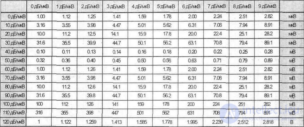
10. Recalculation of the signal level in dB / µV (dB / µV) to voltage
Bibliography
1.1. GOST 7845-79. Broadcast television system. Basic parameters, measurement methods.
2.1. A.A.Shur. Near and far television reception. M .: publishing house "Radio and Communication" 1991.
2.2. A.M. Varbansky. Transmitting television stations. M .: publishing house "Svyaz", 1980.
2.3. GOST 18198-85. Television receivers. General technical conditions.
2.4. G.V. Babuk, M.G. Lokshin, I.I. Mikolaytis. Selectivity of television receivers on the mirror channel. (Telecommunication 1983.- N 7.- p. 28-33).
2.5. GOST 11216-83. Distribution networks receiving television and radio broadcasting systems. Basic parameters, technical requirements, methods of measurement and testing.
2.6. Television and sound VHF FM broadcast networks: A Handbook. / M.G.Lokshin, A.A.Shur, A.V.Kokorev ,. R.A. Krasnoschekov.- M .: Radio and communication, 1988.
3.1. GOST 11289-80. Television reception antennas. Types Main settings. General technical requirements.
3.2. B.G.Tsibaev, B.S.Romanov. Antenna amplifiers. M .: Soviet Radio, 1980.
3.3. G. I. Bornichuk, V.I. Bulych Amateur radio about television antennas. M .: DOSAAF, 1997.
6.1. Benkovsky 3., Lipinsky E. Amateur antennas of short and ultrashort waves. M .: Publishing house "Radio and communication", 1983.
6.2. L.M. Kapchinsky. Design and manufacture of television antennas. M .: Publishing house "Radio and communication", 1995.
6.3. Kari Rothammel. DDR, Berlin, 1984.
6.4. L.S. Esyutin. Elements of transmission lines of high-frequency energy and antenna. M .: Publishing House of Moscow University, 1969
6.5. N.A. Reushkin. Collective television reception systems. M .: Radio and Communication, 1992.
6.6. S.Ye. Zagik, A.M. Kapchinsky TV receiving antennas. Gosenergoizdat, 1960
7.1 GOST 19463-74. TV broadcast image transmissions. The main channels of the image radio-relay and cable communication lines. Main settings. Measurement methods.
GOST 24330-80. Television color image receivers. Main settings. GOST 24331-80. Television color image receivers. Measurement methods. GOST 21879-76. Television broadcasting.
7.2. Recomendation and Reports of the CCIR, 1986. XVI Plenary Assembly, Dubrovnik, 1986.-
Vol. XI, XII:
MKKP. Report 624-3. Characteristics of television systems.
CCIR. Recommendation 568. A single value of the signal-to-noise ratio for all
television systems.
CCIR. Recommendation 500-3. Methods of subjective quality assessment
television images.
CCIR. Recommendation 567-1. Characteristics of television communication channels,
intended for international broadcasts. 7.3 Catalogs of firms DIPOL, TERRA, Pomax, AST, Sphore Wimat, Wiedyska, SOWAR, NASA
Elektronik, Telegamax.

Comments
To leave a comment
Television and antennas. Theory. Broadcast and cable. Digital and analog
Terms: Television and antennas. Theory. Broadcast and cable. Digital and analog