Lecture
ASP-4A, ASP-8A and the like flat antennas are widely used for receiving television programs. Operating experience has revealed both positive and negative qualities. These antennas have long been used abroad and only since the mid-90s began to be widely used in the CIS countries. In advertising brochures ASP-8A (ASP-4A) antennas are called broadband or all-wave, but reliable reception of television programs is possible mainly on the UHF band. When receiving channels of the same wavelength range, due to the use of fan-shaped vibrators, the lack of gain is strongly affected. The use of an antenna amplifier as part of the antenna significantly increases the operating parameters and expands the scope of the antenna.

To expand the reception range in the meter range, the upper short vibrator is changed to a vibrator 45-60 cm long (Fig. 3. 43). This improves the reception of 6-12 channels of the meter range. This upgrade leads to a mismatch of the antenna and a decrease in the overall gain. If necessary, you can compensate for the loss of gain by replacing an amplifier with a high gain. However, an even greater mismatch may occur and, as a result, self-excitation. Self-excitation is manifested in the appearance of ns images of wide moving vertical stripes, multi-contourness, etc. The best results are achieved by installing two (1 and 4) long vibrators (instead of short ones) in ASP-8A antennas - the error in this case is insignificant.
If the reception of channels of the meter range (1 - 12) is not satisfactory, this antenna is better to use for receiving decimeter waves, and for receiving in the meter range to install an additional antenna.
The advantages of this antenna should include a relatively narrow radiation pattern in the vertical plane, making the antenna less susceptible to interference from electric transport and other sources. Therefore, it is advisable to receive television programs using such antennas in the city.
The negative qualities of these antennas appear when the field intensity in the vertical plane is uneven. In this case, the energy received by the upper (or lower) vibrator is again re-emitted into space by the lower (or upper) vibrator. Therefore, when installing such an antenna, it is necessary to find the optimal location, to make its orientation in space. Otherwise, the quality of image reception of some television programs cannot be improved.
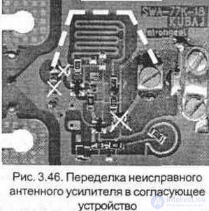
It should be borne in mind that such antennas with amplifiers, having a high gain, amplify and interference. With a large signal level at the receiving point, as well as using an antenna near the television center, self-excitation occurs on some TV channels. In these cases, it is recommended to use a plate amplifier with a lower gain, or instead install a matching device or redo an existing (or better defective) amplifier, as shown in Fig. 3. 46.
To increase the gain in the frequency band of the received channels, a set of passive elements (directors) are installed that are installed before the active ones. The design (location and size) of directors in some antennas is intended more for beauty, and not for enhancing the amplifying and directional properties of antennas. In reality, the dimensions of these elements (in the ASP-8A antenna, the number of passive elements from 1 to 7) do not exceed 0.15 m.
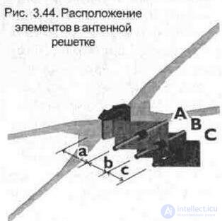
The amplitudes and phases of the currents in the passive elements depend on the diameter, length and relative position of these elements with respect to each other and to the active vibrator. With an increase in the number of directors, the directional properties of the antenna improve and its gain increases. Selecting the distance between the elements and their length, they tune the antenna in a certain frequency band. The approximate arrangement of elements is shown in fig. 3. 44, and their dimensions relative to the average wavelength l cf. used television channel (group of channels) are given in table. 3. 4.
Table 3. 4. The dimensions of the elements of the antenna (Fig. 3. 44)
Elements and distances | C (l) | B (l) | A (l) | c (l) | b (l) | a (l) |
Dimensions | 0.45 ... 0.48 | 0.44 ... 0.46 | 0.43 ... 0.45 | 0.1 ... 0.12 | 0.1 ... 0.15 | 0.1 ... 0.2 |
For example, for the 30th television channel lf = 0.549 m., Therefore, the estimated length of the vibrators C, B and A will be 0.549 x 0.45 - 0.24 m, for the 60th channel l cf — 0.382 m., Then the length vibrators equal to 0.382 x 0.45 - 0.17 m.
Some amateurs independently produce directors for such antennas according to calculated data taken from reference books. However, the setup process requires the use of special equipment and conditions, which in practice is quite difficult to implement. Similar difficulties (lack of amplification in the frequency band of the meter range) also arise when using log-periodic antennas of foreign production for reception, the reception range of which depends on the geometrical dimensions. To expand the reception in the area of meter channels, the geometrical dimensions of the last 2-3 elements are increased to a value equal to l / 2 of the required reception channel. However, such a restructuring of the antenna must be accompanied by a change in the distance between the enlarged elements.
When operating antennas with an antenna amplifier, special attention should be paid to the feeder feeder used. It is necessary to use a new coaxial cable, since over time its parameters deteriorate. If the cable has been in the open air for a long time, then the protective screen is oxidized. And in these antennas along the cable to the amplifier comes in addition to the signal supply voltage. At the old cable, in the places of bends, the central conductor may short circuit to the protective sheath of the cable, which leads to failure of the power supply unit stabilizer. Sealing the antenna amplifier is not good enough (the body over time under the influence of sunlight and moisture deforms), so special attention should be paid to the elimination of cracks and cracks in the antenna box (installation location of the antenna amplifier).
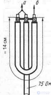
Attention should be paid to the cable of reduction, which should fit the amplifier below. Otherwise, the moisture on the cable drops falls inside, which leads to the failure of the plate antenna amplifier. In those cases, if this happens and there is no possibility to purchase a new amplifier - it must be dismantled and connect a drop cable through a matching loop (Fig. 3. 45), which is about 14 cm in size (for the UHF range).

Comments
To leave a comment
Television and antennas. Theory. Broadcast and cable. Digital and analog
Terms: Television and antennas. Theory. Broadcast and cable. Digital and analog