Lecture
Receiving television antennas convert the energy of electromagnetic waves into RF energy supplied via a feeder (usually a coaxial cable) to a television receiver. The quality of the received signal largely depends on the antenna, so it is necessary to know the basic parameters of the antennas and the features of their structures. At the place of installation of the antenna can be:
- room intended for installation indoors;
- built-in, installed inside the TV;
- outdoor, intended for outdoor installation. Depending on the range properties of the antenna are:
- single channel intended for the reception of one television channel;
- multi-channel, designed to receive multiple television channels;
- band intended for receiving one or several television bands.
A wide selection of various designs of television antennas is represented on the CIS markets by both domestic and foreign manufacturers. The documentation provided often contains more advertising than objective information, which could be used to determine their quality indicators. The following are the parameters and design features of TV antennas.
3. 1. Parameters of TV antennas
An antenna is a device that radiates high-frequency energy supplied to it in the form of electromagnetic waves into the surrounding space (transmitting antenna) or receives high-frequency energy of free oscillations (receiving antenna) and turns it into electromagnetic oscillation energy fed by a feeder to the input of the receiving device.
The transmitting and receiving antennas have the reciprocity property, that is, the same antenna can radiate or receive electromagnetic waves, and in both modes it has the same properties (parameters).
The transmitting antennas impose additional requirements related to the large input power of RF energy, therefore, structurally receiving antennas are simpler than transmitting.
Reciprocity properties are widely used to determine the characteristics of antennas, since some parameters are easier to determine in transmission mode than in reception mode. Each antenna has a number of specific characteristics necessary to assess its quality.
The main parameters of receiving television antennas include the following:
WORKING RANGE OF FREQUENCIES (bandwidth) is a frequency interval in which all the main parameters of a receiving television antenna are sustained: matching, gain, protection factor, etc. The frequency spectrum is taken as the frequency range (determined by the received television channels), at whose boundaries the power received signal is reduced by no more than two times.
The DIRECTION DIRECTION of the receiving antenna characterizes the dependence of the EMF induced in the antenna by the electromagnetic field on its orientation in space. It is under construction in polar (spherical) - fig. 3. 1 or in a rectangular system (Fig. 3. 2) coordinates in two characteristic planes (horizontal and vertical).
When turning the antenna in one direction or the other from the zero direction, the values corresponding to the E / E max ratio are plotted on the diagram. If we square in the relative values of the EMF corresponding to different directions of signal arrival, then we can construct a radiation pattern for power.
The petal corresponding to the maximum signal or zero direction is called the main or main one, the others are lateral or rear ones (depending on the location relative to the main lobe).
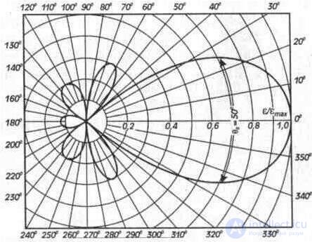
Fig. 3. 1. The polar pattern of the antenna in the polar coordinate system
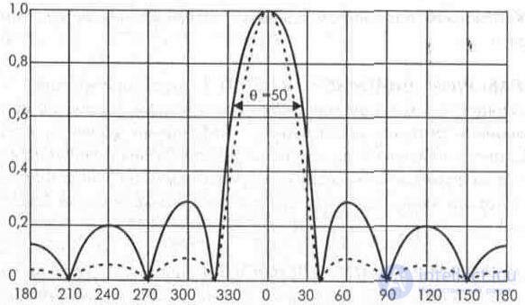
Fig. 3. 2. Antenna pattern in a rectangular coordinate system
For convenience of comparison of radiation patterns of different antennas, they are usually normalized, for which the maximum value of the EMF is taken as a unit.
The main parameter of the radiation pattern is the angle of the solution (width) of the main lobe, within which the emf induced by the electromagnetic field in the antenna drops to the level of 0,707, or the power falling to the level of 0.5 from the maximum. The width of the main lobe is judged on the directional properties of the antenna. The smaller this width, the greater the directivity of the antenna.
The shape of the radiation pattern depends on the type and design of the antenna. The directional pattern of a half-wave vibrator in a horizontal plane resembles a figure eight, and in a vertical plane it looks like a circle. The antenna "wave channel" in its radiation pattern has a pronounced main lobe, and with an increase in the number of directors in the antenna, the main and side lobes narrow, and the directional properties of the antenna improve.
COEFFICIENT OF DIRECTED ACTION (KND)
characterizes the directional properties of the antennas and is a number indicating how many times the signal power received by the antenna is greater than the power that the reference antenna will receive (half-wave vibrator). KND (D) depends on the width of the antenna pattern in the horizontal and vertical plane. The approximate formula is:
D = 41200 * k ^ 2 / H * V, (3. 1)
where k is a coefficient equal to 1 °;
H is the width of the radiation pattern in the horizontal plane, degrees;
V is the width of the radiation pattern in the vertical plane, deg.
In practice, it is often necessary to estimate the directivity factor with respect to a dipole antenna, rather than a non-directional one. In this case, the KND value calculated by the specified formula should be reduced by 1, 64 times. To calculate the directivity factor in decibels, take 10 decimal logarithms of the value of the directive value [D (dB) = 10 Ig D] and, for the calculation with respect to the dipole, reduce the obtained value by 2.15 dB [W].
KND is related to the power gain Gp by the ratio:
Gp = D * n, (3.2)
where: n is the efficiency of the antenna.
At meter and decimeter waves, the efficiency for receiving antennas is close to unity — about 0.95 [3.3].
ANTENNA AMPLIFIER COEFFICIENT indicates how much the signal induced in it exceeds the signal level on the reference antenna. A half-wave vibrator or an isotropic antenna (a completely non-directional antenna having a spatial pattern in the form of a sphere) is taken as a reference antenna. In reality, there are no such antennas, but it is a convenient benchmark with which you can compare the parameters of existing antennas. The gain of a half-wave vibrator relative to an isotropic antenna is 2. 15 dB ( 1. 28 times the voltage or 1. 64 times the power). Therefore, if it becomes necessary to recalculate the antenna gain by voltage or power relative to an isotropic antenna, then it is necessary to divide the known value by 1. 28 or 1. 64, resulting in a gain relative to the half-wave vibrator. If the G antenna is specified in decibels relative to an isotropic antenna, then to recalculate it relative to a half-wave one must subtract 2. 15 dB.
For example, if with respect to an isotropic antenna G = 6, 5 dB, then with respect to the half-wave vibrator G = 6, 5 - 2, 15 = 4, 35 dB.
When comparing antennas, one should pay attention to whether the gain is expressed in terms of voltage or power:
Gp = Pa / Re = 10lg Ra / Re (dB); (3.3) Gu = Ua / Ue = 20 Ig Ua / Ue (dB); (3.4)
where Pa is the power received by the antenna;
Ra is the power received by the reference antenna;
Ua is the antenna voltage;
Ue is the voltage on the reference antenna.
The average antenna gain in the working frequency band is the arithmetic average of the gain in decibels measured at the mid frequencies of each channel within the working frequency band, as well as at the extreme frequencies of that band.
Uneven gain - the ratio of the maximum gain to the minimum in the frequency band of the received channels.
THE PROTECTIVE ACTION COEFFICIENT (CPD) determines the ANTENNA INTERRUPTION - the ratio of the voltage received from the antenna at a consistent load when received from the rear or side direction to the voltage on the same load when received from the main direction.
Immunity in decibels is determined by the formula:
KZD = 20 Ig E rear / E ch. (dB) (3.5)
In foreign sources, the noise immunity is expressed by the anteroposterior ratio (PZO), which characterizes the antenna directivity for 0 ° and 180 ° angles. PZO is the ratio of the voltages that occur at the input of the antenna when irradiated from these directions:
PHL = U0 / U180: (3.6)
For the same antenna, the magnitude of the PDC and PZO are equal in magnitude (the magnitude of the CPD is negative). There is a definition of noise immunity, as the side lobe level (UBL) of the radiation pattern is the ratio of the emf when received from the maximum of the largest side lobe to the emf when received from the maximum of the main lobe. The level of side lobes, are in relative units or percentages.
UBL = (Emaks.bok / Emaks.gl.) • 100%. (3.7)
When designing antennas The level of side and rear lobes tend to be minimized in order to improve the noise immunity of antennas.
INPUT RESISTANCE OF ANTENNA characterizes its impedance properties at the supply point (at the point of connection of the feeder) and is equal to the ratio of voltage to current at the input of the feeder. In general, the input impedance of the antenna Zin contains the resistive Rin and reactive Xinh (capacitive or inductive) components:
Zвx = Rвx + Хвх (3.8)
The smaller the reactive component Hvc and the closer Rin to the wave impedance of the line feeder, the better the antenna is matched. Failure to comply with the matching conditions leads to the appearance of multiple reflections of signals in the antenna feeder, manifested in the form of repeated, horizontally shifted images on the TV screen and a partial loss of power of the received signals in the feeder.
To reduce the power loss, the antenna must be tuned to resonance with the frequency of the received channels. If the antenna works in a wide range of TV channels, it should be tuned to the middle frequency of the range. In practice, the adjustment is reduced to the selection of the geometric dimensions and elements of the antenna, as well as the location of the terminals to which the feeder line is supplied. Antenna resonance is achieved when an integer number of half-waves fit the length of the vibrator. If the number of half-waves stacked along the vibrator is odd (l / 2, H * l / 2, etc.), then the input resistance is small (from 73 Ω with the length of the vibrator l / 2 to 120 Ω with a larger number of half-waves). If the number of half-waves is even l , 2 * l, 3 * l, etc.), then the input resistance is large (from 400 - 500 Ohm to 1 - 2 kOhm, depending on the diameter of the conductors).
At frequencies below the resonant reactive component has a capacitive, and at frequencies above the resonant - inductive. The input impedance of the antenna also depends on objects located near the antenna and affecting the field distribution in space, which must be considered when installing the antenna.
The dependence of the input impedance of the antenna on the frequency is called FREQUENCY CHARACTERISTICS The less the input impedance of the antenna changes with a change in frequency, the spike its bandwidth.
COFFICIENT WAVE RATIO (IPM) shows the degree of matching the receiving antenna with the feeder (cable) reduction. It is numerically equal to the ratio of the minimum voltage (node) of the line to the maximum voltage (antinode), which would have occurred when measured along the feeder when the antenna operates in the transmission mode:
KBV = Umin / Umax (3.9a)
An IPM is expressed in relative units: the larger the IPM value, the more efficient is the transmission of the signal from the antenna to the TV. Full coordination will be in the case when the antenna resistance Ra and the impedance of the feeder RF are equal (Ra = RF). For a purely traveling wave, the current and voltage along the length of the feeder have neither a minimum nor a maximum, and an IPM is equal to one. Such a matching mode is practically difficult to obtain, it is quite enough to assume an IPM> 0. 5, which corresponds to a decrease in the power of the received signal up to 10% [3. 3]. The higher the value of the IPM (in antennas of various designs is within 0, 25 ... 0, 6), the more efficient the transmission of the signal from the antenna to the TV, the higher the reception quality.
COEFFICIENT OF STANDING WAVE (CWS) - the reciprocal of KBV:
SWR = 1 / IPA. (3. 96)
REFLECTION RATIO is the ratio of the amplitude of the reflected wave to the amplitude of the incident wave:
IPI = IUotp / Unad.l (3.10)
The ACTIVE (EFFECTIVE) LENGTH of the antenna characterizes the ability of the receiving antenna to extract electromagnetic energy from the surrounding space and is determined by the ratio of the emf induced in the antenna to the electric field strength at the location of the receiving antenna:
ld = U / E (3.11)
where U is the EMF value at the antenna terminals, mV;
E - electric field strength at the reception site, mV / m. The effective antenna length (ld, in meters) is related to the gain and input impedance of the antenna as follows [6. one]:
ld = (l / 3.14) ( G * Ra / 73.1) ^ 0.5, (3.12)
where l is the average wavelength, m;
G is the antenna gain;
Ra is the antenna resistance. Ohm;
.
The effective length of a half-wave vibrator is:
ld = l / 3.14 = 0.32 * l (npu G = 1, Ra = 73, 1 ohm). (3.13)
In general, the output voltage of the antenna, matched to the receiver, is defined as
U = lеE / 2, (3.14)
where: U is the EMF value at the antenna output, µV;
E is the electric field strength at the reception site, µV / m.
Usually, the concept of effective length is introduced for vibrators with an arm length lp <= 0.7l.

Comments
To leave a comment
Television and antennas. Theory. Broadcast and cable. Digital and analog
Terms: Television and antennas. Theory. Broadcast and cable. Digital and analog