Lecture
Individual antenna amplifiers are designed to increase the level of a television signal when receiving broadcasts of black and white and color images. They are designed to work with television receivers of any type and class. Typically, the input and output of the amplifier is designed to connect a feeder with a characteristic impedance of 75 Ohms. Individual antenna amplifiers depending on the amplified
Frequencies are made for the ranges of MB, UHF or MB + UHF. According to the design, the amplifiers are placed on the mast (in the immediate vicinity of the antenna) or installed near the television receiver.
4.3.1. TV amplifier MB range UTDI I-II, UTDI III
Individual range television amplifiers are designed to amplify signals in the meter wavelength range. The UTDI-I-II unit amplifies the television signals from 1 to 5 television channel, the UTDI-III block from 6 to 12 television channel.

Fig. 4. 27. The appearance of the amplifier kit UTDI-I-II, UTDI-III
Electrical parameters of the amplifier unit UTDI-I-II
Gain, dB, not less ........................................... ............................ 14
Irregularity of the frequency response, dB, no more ........................................... ........................... 3
KBV on the exit side, no less ........................................... ................................ 0.6
Noise ratio, dB, not more than ........................................... ................................ five
Electrical parameters of the amplifier unit UTDI-III
Gain, dB, not less ........................................... ......................... 12
Irregularity of the frequency response, dB, no more ........................................... ........................... 3
KBV on the exit side, no less ........................................... ................................ 0.6
Noise ratio, dB, not more than ........................................... ................................ 6
Structurally, the amplifier consists of three blocks - two blocks of A2 amplifiers (UTDI-I-II) and A1 (UTDI-III), which are installed directly on the antenna mast or in close proximity to them and the power supply unit with an A3 signal addition device installed television receiver. Television
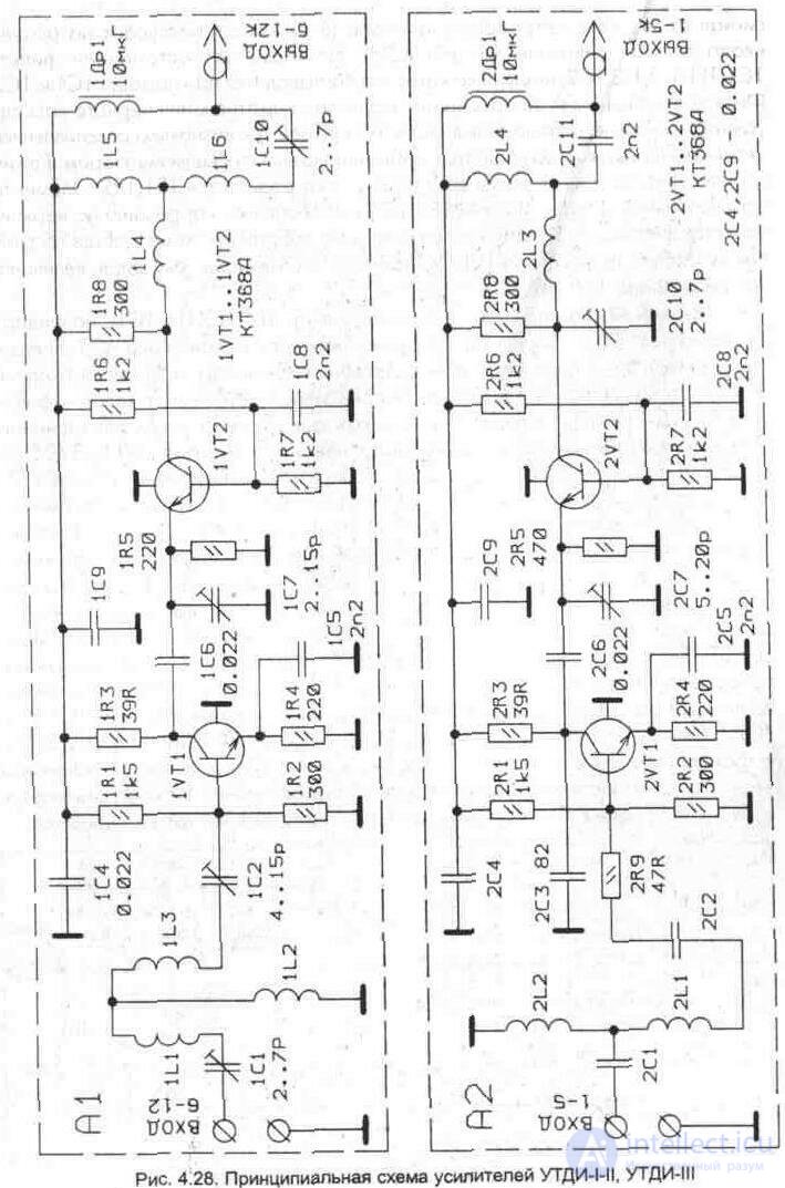
the signal from the antenna meter range (6-12 channel) is fed to the input connector of the amplifier unit A1 (Fig. 4. 28). At the input A1, the filter 1С1, 1L1,1L2,1L3, 1С2 is installed, which is configured using 1С1 and 1С2. The filter provides matching of the input impedance of the first stage of the amplifier, performed on a 1VT1 transistor (KT368A), with the characteristic impedance of the antenna. The first stage of the amplifier is assembled according to the scheme with a common emitter. The transistor current mode is determined by resistors 1R1, 1R2. Elements of negative feedback 1R4, 1C5 carry out the correction in the upper frequencies of the range. The second amplifier stage is assembled according to the common base scheme. The mode of operation of the transistor 1VT2 (KT368A) DC is given by the values of the resistors 1R6, 1R7.
The output signal through a bandpass filter 1L4, 1L5, 1L61C10 on the feeder reduction is fed to the input of the device of the addition of signals of the block AZ. The television signal from the antenna of the meter range (1-5 channel) is fed to the input connector of the A2 amplifier unit. The description of the concept is similar to the amplifier UTDI-III (A1), with the exception of some elements and their designations. The stabilized power supply unit is made on 3VT1, 3VD5 elements according to the traditional parametric stabilizer scheme. The primary winding ZT1 is connected in series with the power source of the television receiver, which allows to reduce the dimensions of the step-down transformer. Power is supplied to the A3 unit when you turn on the TV. Through 3L6, 3L7, the supply voltage of 10, 5 V is applied to the connecting connectors (CAT-G, CAT-W) and fed to the amplifier blocks through the feeders. The signal combining device is a filter of the upper 3C1, 3L1, 3C2, 3L2, 3C3 and low frequencies ZC6, 3L3, ZC7, 3L4, 3C8, 3L5 and provides isolation between the amplifiers of different ranges, introducing minor losses at operating frequencies. Frequency response of band amplifiers is formed by changing the size of construction tanks (1С1, 1С2, 1С7, 1С10 - UTDI-III amplifier 2С7, 2С10 - UTDI-I-II amplifier and ЗС2. 3СЗ in the signal combining device), as well as changing inductances of band-pass filters of the respective ranges. When the coils are stretched, the frequency of adjustment of the contours increases, and during compression, on the contrary, the frequency decreases.
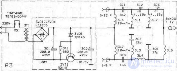
Fig. 4. 29. Schematic diagram of the block A3
4. 3. 2. TV amplifier MB range UTDI I-III
The amplifier television individual range UTDI-I-III is designed to amplify signals in the meter wavelength range from 1 to 12 television channel.
Amplifier parameters
for TV channels ............................................... .................................................. ....... 1-5 ... 6-12
Gain, dB not less than ............................................ ....................... 10 ....... 9
Irregularity of the frequency response in the channel frequency band, dB
no more................................................ .................................................. ................... 3 ........ 3
Noise figure, dB. no more................................................ ........................... 6 ........ 8
Input and output impedance, Ohm ............................................ .................. 75 ...... 75
Power consumption, W, not more than ........................................... ...................................... four

Structurally, the amplifier consists of a functionally complete unit installed directly at the television receiver. Inside the plastic case of the amplifier there are two printed circuit boards (588-1, 588-2) and a network transformer (fig. 4. 31).
A distinctive feature of the performance of these circuits of amplifiers is the implementation of individual elements of band-pass filters by the method of printed wiring. Coordination of the input impedance of the amplifiers and antennas is provided by the elements of C1, L1, L2, W1, C2 and C1, L1, C2, respectively in the III and I-II television bands. The signal from the antenna of the III range (6-12 television channels) is fed to the input connector XS1 of the 588-1 board. The first amplifier stage (board 588-1) is assembled on the transistor VT1 (КТ3109) according to the circuit with a common emitter (Fig. 4. 31). The second amplifier stage is assembled according to the common base scheme. The mode of operation of transistors in a direct current is set by the value of resistors R1, R2 and R6, R7. Elements R4, C4 provide a correction in the upper frequencies of the range. The amplified signal from the collector VT2 through a band-pass filter W2L3W3L4C9 is fed to the connector XP1 "output". The amplifier 1-11 of the range (board 588-2) is made according to a similar scheme, and the output amplified signal through the filter W1L3L4C8 enters the common output connector XP1. The stabilizer is made on the elements VT3VD1C10R9 (board 588-1), and the rectifier on elements VD1-VD4 (board 588-2).

Fig. 4. 31. Schematic diagram of the amplifier UTDI-I-III
4. 3. 3. Amplifier UHF television range "Orbit" TAI 21-41.
The decimeter television amplifier individual "Orbit" is designed to amplify the signals from 21 to 39 television channels and installation on the antenna mast.
Main technical characteristics
Gain, dB, not less ........................................... ......................... 12
Irregularity of the frequency response in the frequency range 470 ... 620 MHz, dB, not more than ................ 3
KBV at the entrance and exit, not less .......................................... .................................. 0, 4
Noise factor, kTo, no more ........................................... .................................. five*
Input and output impedance, 0m ............................................ ....................... 75
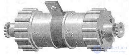
Fig. 4. 32. The appearance of the amplifier "Orbit" TAI 21-41.
Structurally, the amplifier is assembled on a printed circuit board, closed with a metal cover. To protect it from moisture, it is placed in a round plastic case with screw-on lids. At the input and output of the amplifier, connectors (CAT-G antenna sockets) are installed, which are connected (by CAT-W antenna plugs) to the power supply and antenna. The amplifier is powered by a feeder drop from a power source installed near the TV.
Accepted by the antenna signal UHF is fed to the input of the amplifier through a bandpass filter at C1W1 (Fig. 4. 33). Elements W1 - W3 are made by printed wiring (strip lines in the integrated design). A two-stage amplifier is made of transistors VT1, VT2 (КТ3101А), connected according to the scheme with a common emitter. Negative feedback on the current provides the elements of R4C5C6 and R8C8C9, carrying out the correction in the upper frequencies of the range. The modes of the transistor VT1 DC provide the elements of R1, R2, and the transistor VT2 - resistors R5, R6. The isolation of the power provide filters R2C2, L1C7.
* To recalculate the noise figure, you must use the nomogram in the appendix. 2
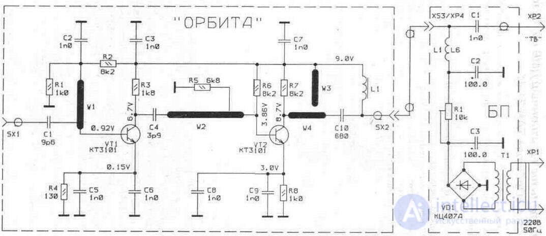
Fig. 4.33. Schematic diagram of the amplifier "Orbit" TAI 21-41.
4. 3. 4. Amplifier UTD UHD television range -IV-V
The UTDI-IV-V television decimeter amplifier provides amplification of signals in the decimeter wave band from 21 to 41 television channels.
Main technical characteristics
Gain, dB, not less ........................................... ............................ 14
Irregularity of the frequency response in the frequency range 470 ... 638 MHz, dB, not more than ................ 3
KBV at the entrance and exit, not less .......................................... .................................. 0, 4
Noise factor, kTo, no more ........................................... .................................. five*
Input and output impedance, Ohm ............................................ .................... 75
Power consumption from a network, W, no more ......................................... ............. 3
Supply voltage, V, at a frequency of 50 Hz .......................................... ...................... 220 + -22
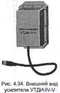
Structurally, the amplifier consists of two blocks - an amplifier block mounted on the antenna mast and a power supply installed directly at the television receiver.
The signal from the DMV antenna is fed to the “input” terminal of the amplifier unit and then to an HPF (1-C1, 1-L1, 1-C2, 1-L2, 1-СЗ, 1-L3), which suppresses the signals located below the decimeter range , and ensures matching of the input impedance of the first stage of the amplifier, performed on the transistor 1-V1 (КТ3101А-2), with the characteristic impedance of the antenna. (Fig. 4. 35) The amplifier cascades are assembled according to the scheme with a common emitter. The stabilization of the transistor DC mode is carried out through resistors 1-R1, 1-R2 and 1-R6, 1-R7. Elements 1-C7, 1-C8 provide frequency response correction in the upper frequencies of the range. From the output of the amplifier, the amplified signal is fed to the feeder to the 2-XS1 connector of the power supply. The signal to the input of the television receiver comes from connector 2-XP2 through the separation capacitance 2-СЗ. A decoupling of the power amplifier stages is provided by filters 1-C4, 1-C5, 1-L-5 and 1-C9, 1-L6, to which 10, 5 V are fed through the feeder from connector 2-XS1 of the power supply through 2-L1 The stabilized power supply unit is made on the elements 2-V5, 2-V6 according to the traditional parametric stabilizer scheme.
* To recalculate the noise figure, you must use the nomogram in the appendix. 2
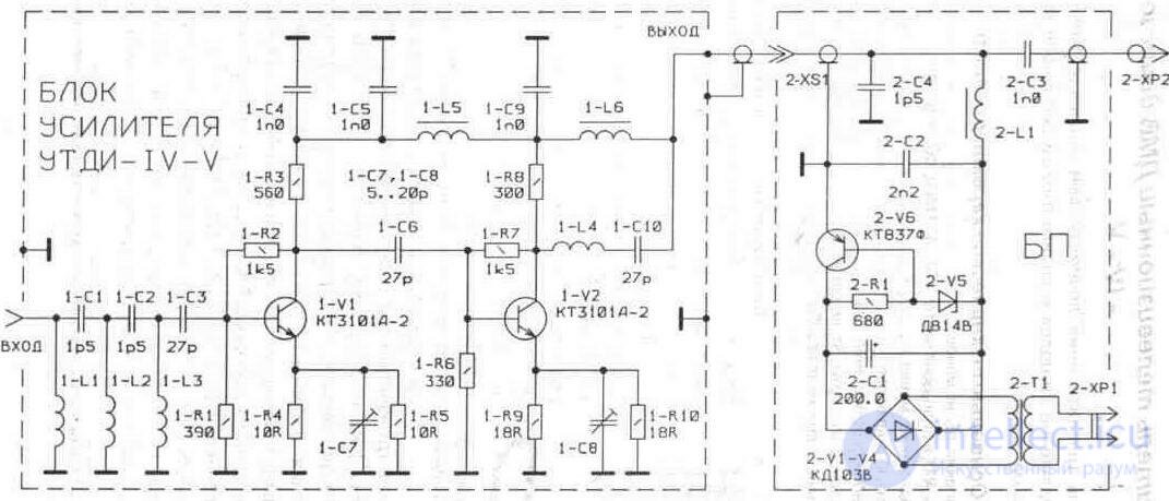
Fig. 4.35. Schematic diagram of the amplifier UTDI-IV-V
4. 3. 5. Amplifier UTAI television UHF range 21 - 41
The amplifier television antenna individual UTAI 21-41 is designed to amplify television signals in the decimeter wavelength range.
Main technical characteristics
Gain, dB, not less ........................................... ............................. 12
Irregularity of the frequency response in the frequency range 470 ... 640 MHz, dB, not more than ................ 3
KBV at the entrance and exit, not less .......................................... ................................... 0, 5
Noise ratio, dB, not more than ........................................... .................................. 7
Input and output impedance, Ohm ............................................ ..................... 75 ± 3
Power consumption from a network, W, no more ......................................... ................ five
Supply voltage, V, at a frequency of 50 Hz .......................................... ...................... 220 ± 10
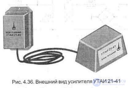
Structurally, the amplifier consists of two blocks:
power amplifier mounted on the antenna mast, and the power supply installed next to the TV. Feeder reduction from the antenna DMV is fed to the terminals X1, X2 (Fig. 4. 37). The high-pass filter C1L1L2C2W1 L3C3 suppresses signals located below the decimeter range.
The amplifier is assembled on transistors VI-V3 (KT371AM). The first amplifier stage, which provides the main amplification at a regulated noise level, is made according to the scheme with a common emitter. The stability of the output stage, performed on transistors V2, V3 with direct connection, provides deep negative feedback (resistors R6, R8). The elements of the filters W1 and W2 (strip lines) are made by printed wiring from the side of the hinged elements. The bandpass filter L6W2L7C9 matches the output of the amplifier with the characteristic impedance of the descent feeder. L8C7 and L5C4 filters provide a decoupling of power amplifier stages, to which 10.5 V are fed to the power supply from the XS2 connector of the power supply unit through L1. The power supply unit contains a power transformer T1, a rectifier V2 - V5, a capacity filter C4, a parametric stabilizer R1V1.
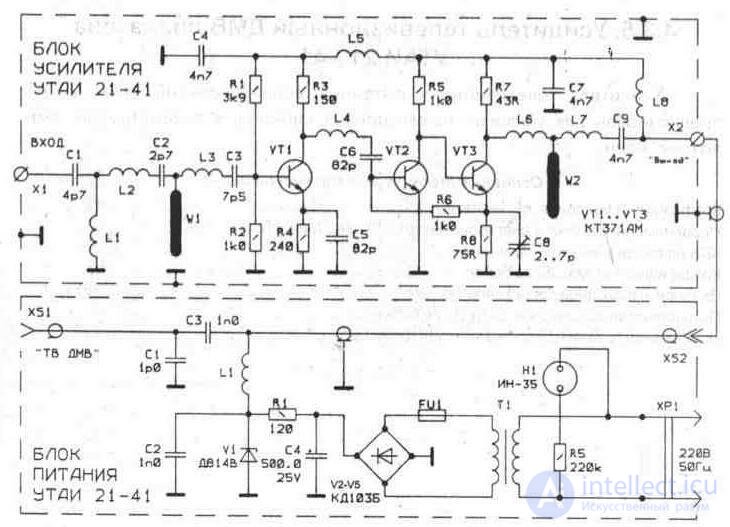
Fig. 4. 37. Schematic diagram of the amplifier UTAI 21-41
4.3.6. Amplifier MB and UHF TV ranges "Sirius"
Broadband antenna amplifier is designed to amplify television signals in the frequency range 48, 5 ... 230 MHz (1 ... 12 channels) and 470 ... 790 MHz (21 ... 60 channels), as well as radio signals in the UHF band ( 65, 8 ... 73, 0 MHz). It is used to improve the quality of the image and sound when receiving black-and-white and color television programs in the area of uncertain reception and is designed to work in enclosed spaces.
Main technical characteristics
Gain, dB, not less ........................................... ............................ 15
Gain unevenness, dB, not more than ........................................ 5
Input and output impedance, Ohm ............................................ ...................... 75+ -3
Power consumption from a network, W, no more ......................................... ................ five
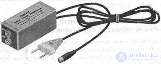
Fig. 4. 38. The appearance of the amplifier "Sirius"
Structurally, the amplifier and power supply are assembled on a double-sided printed circuit board and installed in a plastic case. The signal from the MB antenna is fed to the first amplifier stage from the XS2 connector (Fig. 4. 39) through the L4C14C15L3 filter, and the signal from the UHF antenna from the XS1 connector via L2C9. Diode VD1 protects the input stage from overloading local station signals. The two-stage aperiodic amplifier is made on microwave transistors VT1, VT2 (КТ3101А), connected according to the scheme with a common emitter. Negative feedback on voltage (R5R7C5, R6R8C6 elements) and emitter correction circuits (R9C10, R10C11, R12C12, R13C13 elements) ensure uniformity of gain in the 48, 5 ... 790 MHz band and correction on the high frequencies. Decoupling from
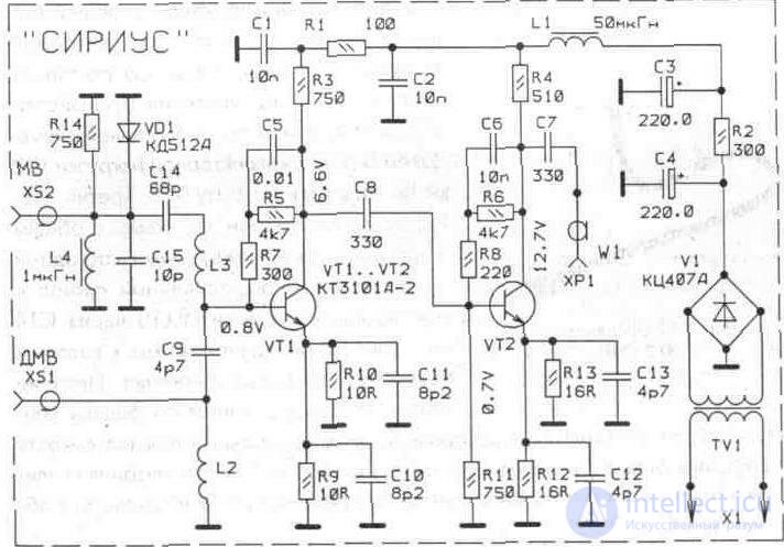
Fig. 4. 39. Schematic diagram of the amplifier "Sirius"
Power noise is provided by L1C2, R1C1 filters. The power supply is made on the elements of Sz, R2, C4.
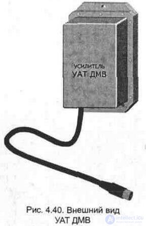
4.3.7. Amplifier TV antenna decimeter wave UAT UHF
Amplifier TV antenna UAT UHF is designed to amplify television signals in the decimeter wavelength range. Structurally made on the PCB, located in a sealed enclosure that allows you to install it on the antenna mast (Fig. 4. 40).
Main technical characteristics
Gain, dB, not less ........................................... ............................ thirty
Irregularity of the frequency response in the frequency range 470 ... 635 MHz, dB, not more than ................ 3
KBV at the entrance and exit, not less .......................................... ................................ 0, 5
Noise ratio, dB, not more than ........................................... ................................ 7
Input and output impedance, Ohm ............................................ ...................... 75
Current consumption at supply voltage of 12V, mA .......................................... ........ 20
At the input of the amplifier (Fig. 4. 41) a band-pass filter L1С1L2 is installed. The signal from the output of the band-pass filter through the capacitance of the Sz enters the first stage (transistor VT1), made according to the scheme with a common base. The amplified signal from the collector load VT1 (L3, L4) through C6 enters the second amplification stage (transistor VT2), made in a similar way. Next, the signal from the collector load VT2 (L6, L7) is fed to the base VT3. The third amplification stage is assembled according to the scheme with a common emitter, the connection between these stages is direct. The amplified signal from the collector load L9, L10 goes through C14 to the output terminals, to which the feeder is fed. The amplifier is powered by a descending feeder through an adapter, in which a separation capacitor and a power filter choke with a 0.05A fuse are installed. To power the amplifier, a separate power source with a voltage of 12V and a current consumption of at least 0. 02A is used.
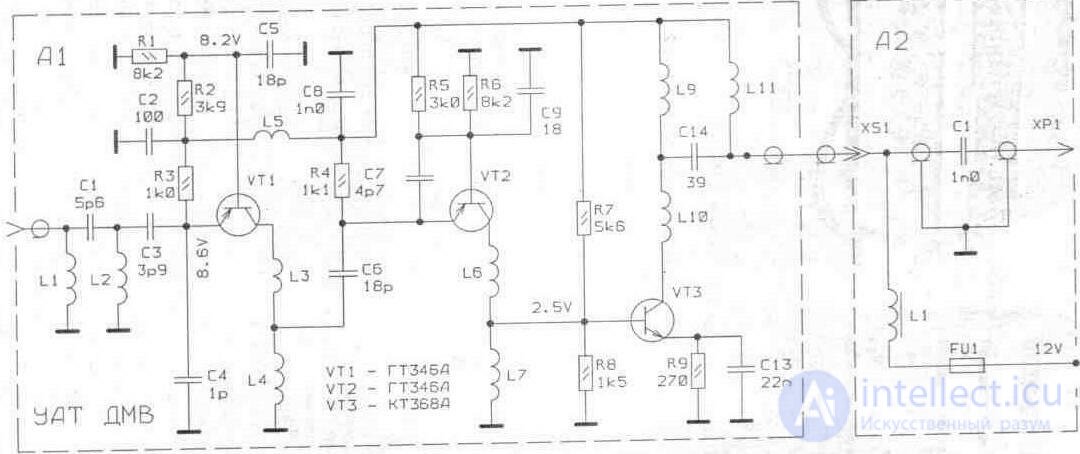
Fig. 4. 41. Schematic diagram of UAT UHF

Comments
To leave a comment
Television and antennas. Theory. Broadcast and cable. Digital and analog
Terms: Television and antennas. Theory. Broadcast and cable. Digital and analog