Lecture
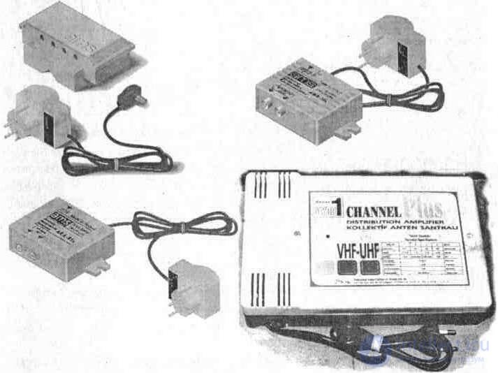
Fig. 5. 1. Appearance of amplifying components.
5.1. AMPLIFIERS INSTALLED ON ROOFS
This type of amplifier is designed to raise the level of the television signal from antennas mounted on high masts. The amplifier case is semi-hermetic, needs protection from direct ingress of moisture, so the amplifier is placed under the roof of buildings (in the immediate vicinity of the antenna mast).
5. 1. 1. AWS-11 AMPLIFIER
Amplifier parameters
Gain:
on the l-ll VHF input (40 ... 110 MHz), dB, no less than ............................... .......................... 26
on input III VHF (160 ... 230 MHz), dB, not less ................................. ....................... 26
on input IV-V UHF (470 ... 800 MHz), dB, not less than ............................... ..................... 24
Noise factor, dB / µV, not more than ......................................... ............................. 3
The depth of adjustment of the signal at the input VHF (l-ll, III), dB ................................... .... -sixteen
Depth of adjustment of a signal on an entrance of UHF (V), dB ............................................... ......... -14
Maximum output signal level, dB, not less than ....................................... 100
Input and output impedance, Ohm ........................................... .... 75
Current consumption (12 V), mA .......................................... ......................................... thirty
Poland's AWS-11 amplifier is used to boost the signal in the VHF - UHF television bands. Made under the scheme with a common emitter on two transistors VT1, VT2 (Figure 5. 3). It is possible to connect up to three antennas - KP (I-II VHF), KL2 (III VHF) and KL3 (IV-V UHF).
To obtain the same signal level at the output, the R1, R3, R5 regulators are installed at the inputs of each of the amplifier ranges. A constant voltage of 12 V to the amplifier (KL4) is fed through a drop feeder from the power supply located next to the television receiver.
If it is necessary to install an additional amplifier (to increase the signal level in the UHF range), it is possible to supply the supply voltage. To do this, close the technological jumper A - A.
The supply voltage through R7, L1, the input terminal KL3 (IV-V UHF) and further along the feeder to reduce the antenna goes to an additional amplifier.
Unused inputs of the antenna amplifier must be bridged with a 75 Ohm resistor.
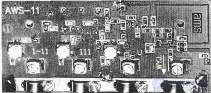
Fig. 5.2. The appearance of the AWS-11 amplifier board
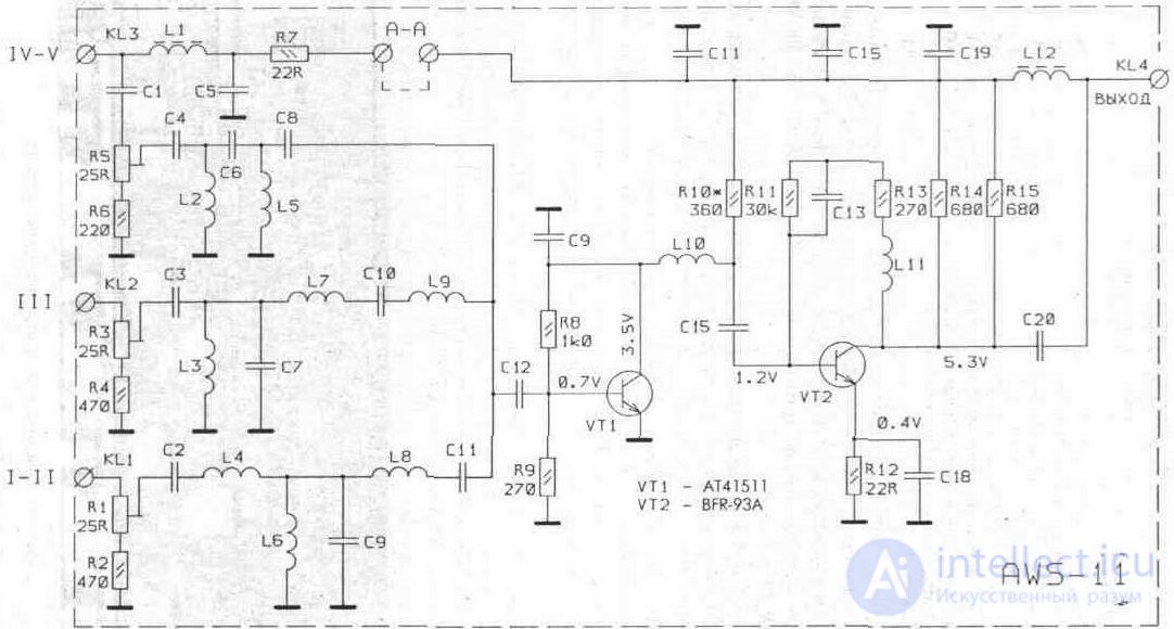
Fig. 5.3. Schematic diagram of the amplifier AWS-11
5.1.2. AWS-16S AMPLIFIER
Amplifier parameters
VHF-UHF input gain (40-800 MHz), dB, not less than ....................... 20
Noise ratio, dB, not more than ........................................... ...........................................four
The depth of adjustment of the signal in the range of VHF (I-II, W), dB ................................... ............12
The depth of adjustment of the signal in the range of UHF (V), dB ........................................... ............ -ten
Maximum output signal level, dB / µV, not less than ....................................... ... 105
Input and output impedance, Ohm ........................................... ............... 75
Current consumption (12 V), mA .......................................... .................................................. .. thirty
Poland's AWS-16S amplifier is used to increase the signal level in the VHF - UHF television bands. The amplifier is made on two transistors VT1, VT2 according to the traditional scheme with a common emitter (Fig. 5. 5). For the correction of the frequency response of the second stage is covered by a negative feedback current (R9, C13).
To equalize the gain of the signal in the appropriate range at the input of the amplifiers are installed resistors R1, R3.
The AWS-16S has two amplified outputs, KL2 and KL3.
A constant voltage of 12 V is supplied to the KL2 terminal of the amplifier via a drop feeder from the power supply located near the television receiver.
If it is necessary to install an additional amplifier (to increase the signal level in the VHF-UHF bands), it is possible to supply the supply voltage, for which it is necessary to close the technological jumpers A - A. The supply voltage through L1, input terminal KL1 and further along the antenna drop feeder goes to the additional amplifier .
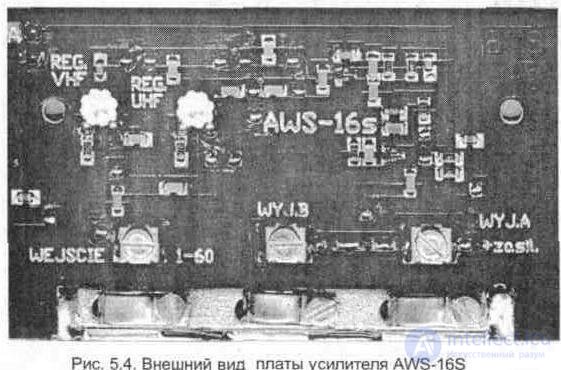
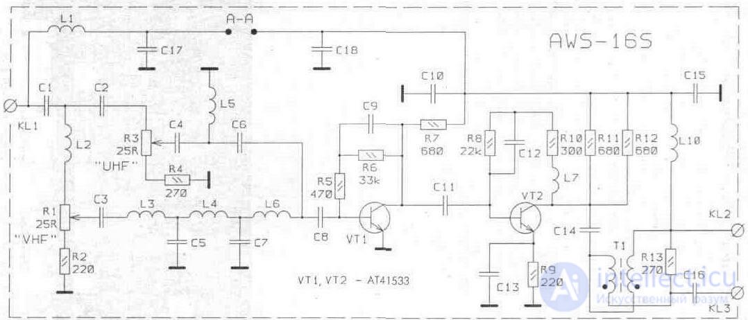
Fig. 5.5. Schematic diagram of the amplifier AWS-16S
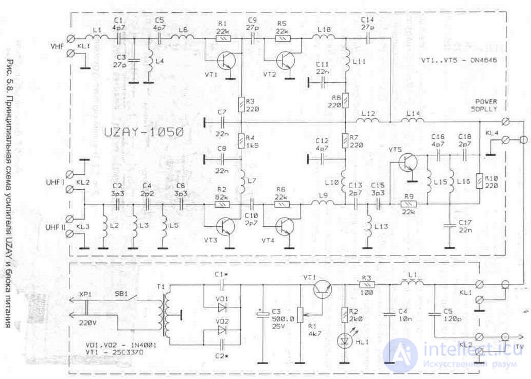
5.1.3. ANTENNA AMPLIFIER "UZAY-1050"
Parameters amplifier UZAY-1050
Gain:
on VHF input (40 ... 230 MHz), dB, not less .................................. ............................. 22
on UHF input (470 ... 860 MHz), dB, not less .................................. ........................... 28
Noise ratio, dB, not more than ........................................... ................................ 6
Maximum output signal level, dB / µV, not less than .............................. 110
Input and output impedance, Ohm ........................................... .... 75
Current consumption (24 V), mA .......................................... ......................................... 120
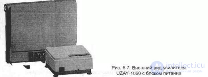
The amplifier UZAY-1050 from Turkey is designed to increase the signal level in the VHF-UHF television bands. It is installed near the antenna on the roof. It is possible to simultaneously connect three antennas to it (one VHF and two UHF bands). The amplifier (Fig. 5. 6.) has two separate amplification channels - VHF and UHF.
Gain in the VHF range provide transistors VT1, VT2, and in UHF - transistors VT3 - VT5. All amplifier stages are powered from the power supply installed at the television receiver (Fig. 5.7).
The stabilizer provides a change in the power supply voltage of the amplifier to adjust the magnitude of the output signal. The schematic diagram of the amplifier is shown in Fig. 5. 8.

5. 2. INTERNAL AMPLIFIERS AND ACTIVE SWITCHES OF SIGNALS (HOME)
Internal amplifiers are designed to compensate for the loss of the signal level at the output of the feeder to reduce television antennas.
Active TV signal splitters are used to amplify and distribute the power of signals fed through the feeder (from antennas, antenna amplifier, subscriber tap of SCTP, etc.) to several television receivers. The following devices are installed directly at the television receiver.
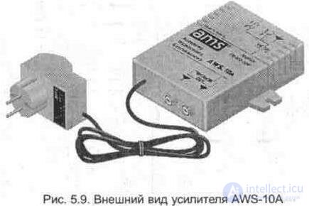
5. 2. 1. AWS-10 INTERNAL AMPLIFIER (AWS-10A)
AWS-10 Amplifier Parameters (AWS-10A)
Gain on the input of VHF-UHF (40 ... 800 MHz),
for AWS-10, dB, not less ......................................... ............................................... 32
for AWS-10A, dB, not less than ......................................... ............................................ 28
Noise ratio, dB, not more than ........................................... ................................ four
The depth of adjustment of the signal in the range of VHF (l-ll, III), dB ................................. -18
The depth of adjustment of the signal in the range of UHF (IV), dB ........................................... -18
The depth of adjustment of the signal in the range of UHF (V), dB ........................................... . -ten
Maximum output signal level, dB / µV, not less than .............................. 110
Input and output impedance, Ohm ........................................... .... 75
Current consumption (12 V), mA, not more than ....................................... ........................... 40
The AWS-10 (AWS-10A) amplifier manufactured in Poland (Fig. 5. 9) is used to compensate for the loss of signal level in the VHF - UHF television bands and is installed directly at the television receiver.
Both amplifiers are made according to the same scheme on transistors VT1, VT2, VT3. To equalize the gain of the signal in the corresponding range on the wideband amplifier input resistors R1, R5 are installed (Fig. 5. 10).
The amplifier circuit has a common cascade of television signal amplification VT2, VT3 and a preliminary cascade for the UHF range on the transistor VT1. The AWS-10A amplifier has two amplified signal outputs, the AWS-10 has one.
The supply voltage is supplied from the internal rectifier VD1, and the alternating voltage is supplied to the contacts 1, 2 of the amplifier board from a separate unit (AC / AC) of the step-down transformer.
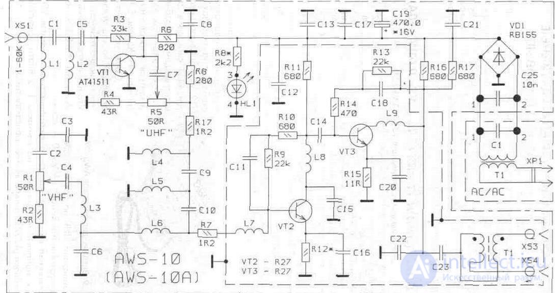
Fig. 5.10. Schematic diagram of the amplifier AWS-10A
5. 2. 2. AWS-12A INTERNAL AMPLIFIER
AWS-12A amplifier parameters
Gain on the input of VHF-UHF (160 ... 800 MHz),
for AWS-12A, dB, not less than ......................................... ....................................... eight
with preamplifier APS-03, dB. no less ................................................ ............ 20
Noise ratio, dB, not more than ........................................... ........................... four
Input and output impedance, Ohm ........................................ 75
AC power ............................................. ........................ 220V / 50Hz
The AWS-12A amplifier manufactured in Poland (Fig. 5. 11) is used to compensate for the loss of the signal level in the feeder drop and is installed directly at the television receiver. It is possible to supply the power supply through L1 to the input connector XS1 for a pre-plate antenna amplifier used in conjunction with the antenna.
The schematic diagram of the amplifier is shown in Fig. 5. 12. The amplification is performed by a cascade performed on a BFP 67 low-noise microwave transistor.
The branching of the signal for supply to the two outputs is carried out using an RF transformer, made on a ferrite core.
The supply voltage is supplied from the internal stabilizer DA1, and the alternating voltage is supplied to the contacts 1, 2 of the amplifier board from a separate unit (AC / AC) of the step-down transformer. The power-on indication is provided by the HL1 LED.
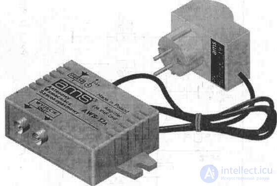
Fig. 511. The appearance of the amplifier AWS-12A
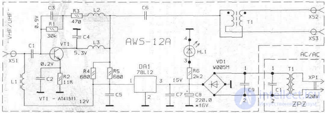
Fig. 5.12. Schematic diagram of the amplifier AWS-12A
5. 2. 3. ACTIVE ANTENNA BRANCHER ARA-01A
Parameters of active antenna splitter ARA-01A
Gain on the input of VHF-UHF (40 ... 800 MHz), dB, not less than ................ 10
Noise ratio, dB, not more than ........................................... ................................ 2
Maximum output signal level, dB / µV, not less than ............................... 105
Input and output impedance, Ohm ........................................... .... 75
Current consumption (12 V), mA, not more than ....................................... ........................... 15
Active splitter television signal ARA-01A made in Poland (Fig. 5. 13). It is used to amplify and distribute the power of a signal coming from antennas, an antenna amplifier, subscriber tap STPP, etc., and to connect two television receivers.
A schematic diagram of the splitter is shown in Fig. 5. 14. The gain provides a cascade on a BFP 67 low-noise microwave transistor.
Power separation and branching of the signal for supply to two outputs is carried out using an RF transformer made on a ferrite core.
The supply voltage to the amplification stage comes from the internal rectifier, made on a full-wave circuit on VD1. The power-on indication is provided by the LED HL1.
The alternating voltage on pins 1, 2 comes from a separate unit (AC / AC) of a step-down transformer.
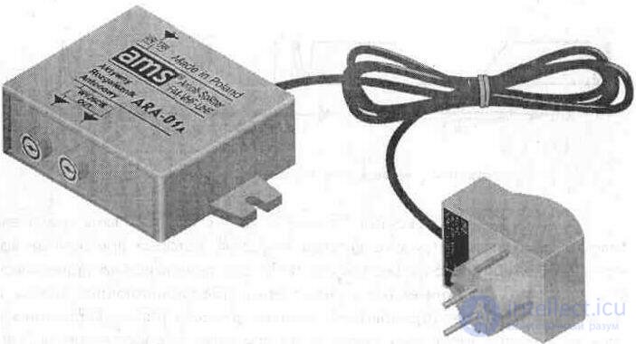
Fig. 5. 13. Appearance of active antenna splitter ARA-01A
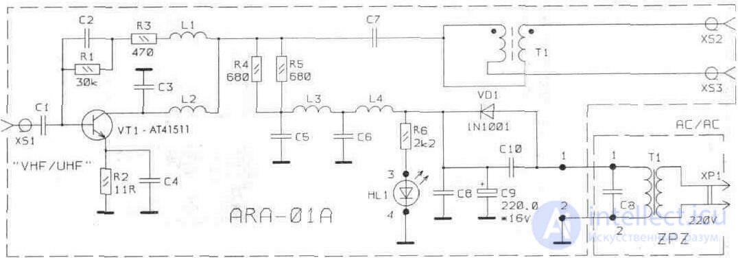
Fig. 5.14. Schematic diagram of the ARA-01A
5.3. BROADBAND MULTIPLE-BAND AMPLIFIERS FOR GENERAL USE ANTENNA SYSTEMS
Apply similar amplifiers as access or house in small systems of collective television reception (SCTP).
Parameters of the antenna amplifier UYDU
Gain at the input of VHF 1 (2-4k, 5-10k), dB, at least .................. 30
on input VHF 2 (5-12k), dB, not less .................................... .............................. thirty
on the input UHF 3 (21-BOC), dB, not less .................................... ............................ 35
on input UNF4 (21-60k), dB, not less ..................................... ........................... 35
Noise ratio, dB, not more than ........................................... ............................. eight
The depth of adjustment of the signal at the inputs of VHF 1, VHF 2, dB ...............................- 14
The depth of adjustment of the signal at the input of UHF 3, dB ......................................... ..... -23
Maximum output signal level, dB / µV, not less than .......................... 125
Input and output impedance, Ohm ........................................... .. 75
AC power ............................................. ........................... 220V / 50Hz
The “UYDU” collective reception amplifier, made in Turkey (Fig. 5.15), is intended to increase the signal level in the VHF-UHF television bands. It is possible to simultaneously connect up to four independent antennas with different polarization of the signal.
The amplifier has two separate amplification channels - VHF and UHF (Fig. 5.16). The first channel has two inputs - VHF 1 (2-4 k), VHF 2 (5-12 k). Gain in this range provide transistors VT1, VT2. Resistor R5 is setting the required signal level at the output of the amplifier.
The UHF channel has three amplification stages (VT3 ... VT5) with adjustment of the signal level at the UHF 3 input. It is possible to power an additional preamplifier mounted on the antenna from the common stabilizer DA1. To do this, close the process terminals A and B.
ATTENTION!
Unused amplifier inputs need to be bridged (connected to the case through a 75 Ohm resistance
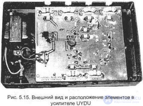
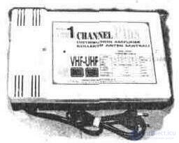
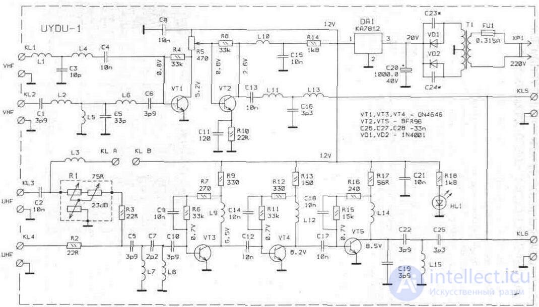
Fig. 5.16. Schematic diagram of the antenna amplifier UYDU
5.4. COMPARATIVE REVIEW OF ANTENNA AMPLIFIERS OF FOREIGN FIRMS
The quality of the television image depends on many factors:
- TV settings;
- the location of the antenna;
- the presence of external interference;
- correct installation and operation of the antenna amplifier.
With a clearly insufficient signal level, the presence of increased attenuation in the feeder reduction, elements of balancing links and separation filters, antenna amplifiers are used (to compensate for losses).
There is an erroneous opinion that by using an antenna amplifier, you can solve all the problems associated with receiving television programs. In fact, this is not the case - the installation of an antenna amplifier is necessary in cases where other elements of the antenna system are intact, and there is an insufficient signal level (directly at the input of a TV receiver or a subscriber tap).
Currently, there are on sale all kinds of antenna amplifiers of foreign firms. Some of them have been discussed above.
In tab. 5.1, 5.2 and 5.3 are given for comparison the parameters of antenna amplifiers and active signal splitters of foreign firms.
Table 5.1. Internal amplifiers
|
Amplifier |
TV channels |
Gain, dB |
Adjustable depth, dB |
Number of inputs |
Number of outputs |
Noise figure dB |
Max. signal, dB / µV |
|
AWS-03 |
1-12 |
28 |
-18 |
2 |
2 |
four |
110 |
|
|
21-60 |
28 |
-ten |
|
|
|
|
|
AWS-03 A ** |
1-12 |
32 |
-18 |
2 |
2 |
four |
110 |
|
|
21-60- |
34 |
-ten |
|
|
|
|
|
AWS-05 A |
1-12 |
24 |
-18 |
2 |
2 |
four |
105 |
|
|
21-60 " |
24 |
- |
|
|
|
|
|
AWS-05 A2 ** " |
1-12 |
32 |
-18 |
2 |
2 |
four |
105 |
|
|
21-60 ' |
32 |
- |
|
|
|
|
|
AWS-06 B |
1-5 |
24 |
- |
3 |
2 |
four |
105 |
|
|
6-12 |
24 |
- |
|
|
|
|
|
|
21-60 |
24 |
- |
|
|
|
|
|
AWS-08 |
21-60 |
thirty |
- |
one |
one |
four |
105 |
|
AWS-08-2 ** |
21-60 " |
40 |
- |
one |
2 |
four |
105 |
|
AWS-08-2R ** |
21-60 ' |
40 |
- |
one |
2 |
four |
110 |
|
AWS-09 |
1-60 |
thirty |
- |
one |
one |
four |
105 |
|
|
|
VHF |
-18 |
|
|
|
|
|
|
|
Uhf |
- |
|
|
|
|
|
AWS-09A |
1-60 |
26 |
- |
one |
2 |
four |
105 |
|
|
|
VHF |
-18 |
|
|
|
|
|
|
|
Uhf |
- |
|
|
|
|
|
AWS-1 |
1-60 |
14 |
- |
one |
one |
2 |
105 |
|
Amplifier |
TV channels |
Gain, dB |
Adjustable depth, dB |
Number of inputs |
Number of outputs |
Noise figure Db |
Max. Signal .. dB / µV |
|
AWS-10 |
1-60 |
32 |
- |
one |
one |
four |
110 |
|
|
|
VHF |
-18 |
|
|
|
|
|
|
|
Uhf |
-14 |
|
|
|
|
|
AWS-10A |
1-60 |
28 |
- |
one |
2 |
four |
110 |
|
|
|
VHF |
-18 |
|
|
|
|
|
|
|
Uhf |
-14 |
|
|
|
|
|
AWS-12A ** |
6-60 ' |
20 |
- |
one |
2 |
four |
105 |
|
AWS-30 |
1-12 |
thirty |
- |
3 |
one |
five |
114 |
|
(with "F" connector) |
21-60 |
28 |
- |
|
|
|
|
|
|
21-60 |
thirty |
- |
|
|
|
|
|
AWS-32 |
1-60 |
32 VHF |
- |
one |
one |
five |
114 |
|
(with "F" connector |
|
34 UHF |
- |
|
|
|
|
Table 5.2. Roof mounted amplifiers
|
Amplifier |
TV channels |
Gain, dB |
Number of inputs |
Number of outputs |
Noise figure Db |
|
AWS-11 |
1-5 |
26 R |
3 |
one |
3 |
|
|
6-12 |
26 R |
|
|
|
|
|
21-60 |
24 R |
|
|
|
|
AWS-11V |
1-5 |
26 R |
3 |
one |
3 |
|
|
6-12 |
26R |
|
|
|
|
|
21-60 • |
24 |
|
|
|
|
AWS-14 S |
1-12 |
24 R |
2 |
one |
3 |
|
|
21-60 • |
24 |
|
|
|
|
AWS-15S |
1-60 • |
24 |
one |
one |
four |
|
|
VHF |
24 R |
|
|
|
|
|
Uhf |
24 R |
|
|
|
|
AWS-16S |
1-60 • |
20 |
one |
2 |
four |
|
|
VHF |
20 R |
|
|
|
|
|
Uhf |
20 R |
|
|
|
|
AWS-17A |
6-12 |
38 R |
3 |
one |
four |
|
|
6-12 |
38 R |
|
|
|
|
|
21-60 • |
30 R |
|
|
|
|
AWS-18 |
1-12 |
30 R |
3 |
one |
four |
|
|
21-60 |
32 R |
|
|
|
|
|
21-60 |
32 R |
|
|
|
|
AWS-18S |
1-12 |
32 R |
3 |
one |
four |
|
|
21-38 |
32 R |
|
|
|
|
|
41-60 • |
32 R |
|
|
|
|
AWS-19 |
21-60 • |
12 R |
2 |
one |
four |
|
|
21-60 • |
12 R |
|
|
|
|
AWS-20 |
1-12 |
30 R |
four |
one |
four |
|
|
6-12 |
30 R |
|
|
|
|
|
21-60 |
30 R |
|
|
|
|
|
21-60 |
30 R |
|
|
|
Table 5.3. Active Antenna Splitters
|
Amplifier |
TV channels |
Number of inputs |
Name of Outputs |
Amplification, dB |
Noise figure, dB |
|
ARA01A |
1-60 |
one |
BUT |
ten |
2 |
|
|
|
|
AT: |
ten |
2 |
|
ARA02A |
1-60 |
one |
BUT |
ten |
2 |
|
|
|
|
AT: |
6 |
2 |
|
|
|
|
WITH: |
6 |
2 |
NOTE TO TABLES:
* - it is possible to transmit voltage to the preamplifier, or to the amplifier mounted in the antenna. These amplifiers are used to amplify the signal in conjunction with a plate (mounted in the antenna) preamplifier. Connecting an antenna without such a preamp is not recommended, because A constant voltage is present at the input of the amplifier to supply power to the preamplifier (lamellar) along the feeder. Failure to do so may result in the internal power supply of the main amplifier (AWS) failing;
** - complete with amplifier UNH range;
R - attenuation adjustment provided

Comments
To leave a comment
Television and antennas. Theory. Broadcast and cable. Digital and analog
Terms: Television and antennas. Theory. Broadcast and cable. Digital and analog