Lecture
Receiving television network consists of a set of individual devices for receiving television programs or systems of collective reception. The former include an indoor or outdoor television aerial, antenna feeder, and television receiver. The Collective Television Reception System (SCTP) consists of one or more directional outdoor antennas installed on the roofs of buildings or masts, of a distribution television network (main feeders, amplifiers, and distribution devices) and a few dozen or hundreds of individual television receivers.
Mastering the UHF waveband for television broadcasting entailed the re-equipment of the SSTP (installation of receiving antennas and UHF converters), and in case of individual reception, the installation of antennas and ACS units into television receivers.
Originally SKTP satisfied the organization of reception (one or two television channels) in the decimeter wave band. But, with the advent of all new television programs broadcasting in the decimeter range (in the absence of cable television), it has become necessary for viewers to purchase individual antennas for receiving programs in this range.
Various designs of antennas of both factory and "handicraft production for receiving in the UHF range appeared. The desire to receive new programs led to the irresponsible acquisition of television antennas of an attractive design, but with dubious or insufficiently suitable parameters (without taking into account the reception features at the TV receivers installation site).
Reception of television programs in cities with multi-storey buildings has features: between closely located buildings, zones with high intensity of delayed signals are formed, and behind high-rise buildings there are shade zones.
Has its features and reception at significant distances from the television center.
Before choosing one or another antenna, it is necessary to decide for itself the question of the expediency of its use, since the reception conditions, antenna location, direct line of sight to the telecentre, building structure, roof, etc., will not always satisfy the quality reception of TV programs .
Before purchasing a television antenna, it is advisable to consult a specialist, and also pay attention to which antenna and how the neighbor’s TV shows. If possible, you should check your TV with a similar antenna, and then decide
2.1. Distribution, meter reception zones (VHF) and decimeter (UHF) waves
A common feature for meter and decimeter waves is that they propagate mainly within the line of sight. The field strength of the waves decreases with increasing distance from the transmitting antenna. At the boundary of the line of sight, fluctuations in the field strength level occur due to the bending of the earth's surface (diffraction phenomenon) and curvature of the wave trajectory due to refraction in the atmosphere (refraction). Due to the reflection from the earth's surface and refraction due to the inhomogeneous structure of the atmosphere, two or more waves with random phases and amplitudes arrive at the receiving point. Meteorological conditions (temperature, humidity, pressure, etc.), terrain, and much more also affect the distribution of meter and decimeter waves.
Since the relative dielectric constant of air in the atmosphere decreases with height, the trajectory of the radio wave turns out to be curved, and the degree of curvature depends on the nature of changes in the electrical properties of the atmosphere. Therefore, the transmission distance of television broadcasting is somewhat larger than the calculated theoretically. Taking into account refraction, the visibility range is increased by about 15% compared to the optical (direct visibility) and is determined by the formula:
r = 4. 12 (H ^ 0.5 + h ^ 0.5), (2.1)
where r is the radio visibility distance, km;
H is the height of installation of the transmitting antenna, m;
h - height of installation of the receiving antenna, m.
FOR EXAMPLE, if Н = 150 m, and h = 10 m, then the visibility range will be r = 4.12 (150 ^ 0.5 + 10 ^ 0.5) = 63.5 km. If the receiving antenna is located on the roof of a nine-story house (h = 30 m), then the range is r = 4.12 (150 ^ 0.5 + 30 ^ 0.5) = 73 km. Consequently, with an increase in the antenna suspension height, the radio visibility range increases.
The area of propagation of meter and decimeter waves can be conveniently divided into three zones: illuminated (zone limited to the line of sight), penumbra and shade.
Under the illuminated area should be understood as a zone of guaranteed reception of television programs (up to 0.8r). This is the space within which the electromagnetic field strength is ensured, which is sufficient for regular and high-quality reception of television signals using any television set. In the near zone (several kilometers from the transmitting antenna), the field strength is characterized by a large irregularity in the form of periodic maxima and minima due to interference at the reception point between the direct and reflected radio wave reflected from the Earth's surface. When installing the antenna, it is necessary to take into account that the field strength varies as shown in the graph of Fig. 2. 2 [2. one].
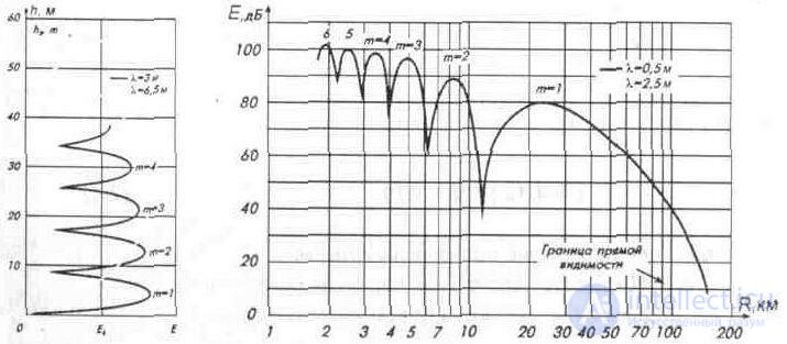
Fig. 2. 2. The location of the maximum field strength
The height of the first maximum nearest to the ground can be determined by the formula below (valid for distances up to 25 km):
hm1 = l * R / 4H, (2.2)
where hm1 is the height of the first maximum field strength, m;
l is the wavelength, m;
R is the distance between the transmitting and receiving antennas, m;
H - the height of the transmitting antenna over the surrounding area, m
And the second maximum (hm2) will be at a height of 3 times, and the third - 5 times greater than the first maximum. For the near zone, the level of the signal is also characteristic, since reception can be carried out from side lobes of the radiation pattern.
With increasing distance from the transmitting center, the field strength decreases, while the effective value of the intensity of the electromagnetic field, Еud, is determined by the equation
Unit = 173 • (P * G * n): 0.5 / R, (2.3)
where Ed is the field strength in free space, mV / m;
R is the distance between the transmitting and receiving antennas, km;
P- transmitter power, kW;
n - efficiency antenna feeder in relative units;
G - gain power of the transmitting antenna
(relatively isotropic antenna). If G is expressed relative to a half-wave dipole, then the factor 1.64 is inserted at the root, and the formula has the form
Un = 222 • (P * G * n ) ^ 0.5I R. (2.4)
To obtain the amplitude value of the field strength, the values obtained in the calculations increase by 2 ^ 0.5, i.e. 1.4 times.
For ease of calculation, in some cases, the field strength is expressed in decibels with respect to the field strength of 1 µV / m, and is denoted dB / µV / m. In this case:
E = 106.9 -20lg (R) + 10lg (P) + 10lg (G) + 10lg (ri), (2.5)
where E is the field strength, dB;
R is the distance between the transmitting and receiving antennas, km;
P- transmitter power, kW;
G is the power gain of the transmitting antenna;
n- antenna feeder efficiency in relative units
Since the height of antennas (transmitting and receiving) in most cases is much less than the distance between them, with distances less than 0.8 of the radio visibility distance, the field strength with sufficient for practical purposes can be calculated using the formula B.A. Vvedensky [2.2]:
E = 2.18 * t * H * h * ( P * G * n) ^ 0.5 / l * R ^ 2 (2.6)
where E is the field strength, mV / m;
R is the distance between the transmitting and receiving antennas, km;
P is the radiated power of the transmitting center, kW;
G is the gain of the transmitting antenna;
n is the efficiency of the transmitting antenna;
H - the height of the transmitting antenna, m;
h is the suspension height of the receiving antenna, m;
l is the wavelength in meters;
t - correction factor taking into account the curvature of the earth's surface.
The formula 2.6 is applied at observance of inequalities:
R <= 0.8r, (2.7) H * h * m / R * l <= 0.1. (2.8)
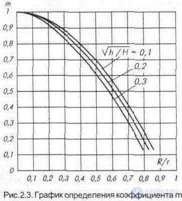
For distances of no more than 25 km, the earth's surface can be considered flat, i.e. we can assume that t = 1 Fig.2.3, for which it is necessary to calculate the radio visibility zone by the formula 2.1, the ratio R / r and (h / H) ^ 0.5.
If the effective radiated power of the transmitting station in the main direction of the antenna
Pe = P • G • n, (2.9)
where Re - effective radiated power, kW;
P - transmitter power at the input of the feeder, kW;
G is the gain of the transmitting antenna power relative to an isotropic antenna;
n- antenna feeder efficiency in relative units;
then formula 2.6 will look like:
E = 2.18-tH-h- (Re) ^ 0.5 * / l * R ^ 2 (2.10)
The possibility of receiving in the penumbra (from 0, 8r to 1, 2r) depends largely on the antenna used. The fact is that the field strength in this zone of the penumbra rapidly decreases with increasing distance from the television transmitter. Reception of a television signal during the day is unstable, there are both fast and slow changes in field strength.
It should be noted that only at short distances from the transmitting station, the receiving antenna is easy to install at the point of maximum field strength. With increasing distance, the height of the first maximum goes up sharply, so the receiving antenna has to be installed as high as possible.
The reception range is strongly influenced by the terrain. The most difficult reception conditions are in rugged terrain and in mountainous areas: multiple reflections from the peaks and slopes of the mountains cause the image to be multi-edged on the screen of a television receiver. Reception of signals behind the mountains, hills, as well as in the lowlands and ravines is practically impossible. Therefore, in some mountainous settlements, it is possible to receive TV signals only when using television repeaters. The reception of TV signals is also influenced by weather conditions, which lead to significant fading of the signal level due to inhomogeneities of air masses (temperature, humidity, pressure) continuously changing in time.
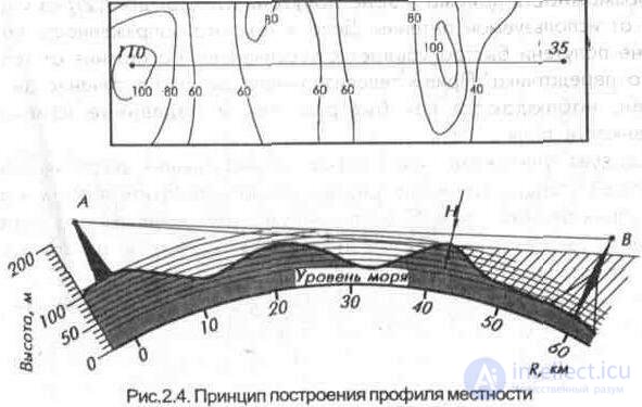
In mountainous areas and on rough terrain, the boundary of the reception area is determined by the presence of direct visibility (although in some places, due to the effect of amplifying signals with wedge-shaped obstacles, it becomes possible to receive television programs at distances far exceeding the line of sight distance). To do this, on the topographic map, a profile of the route is constructed taking into account the presence of natural and artificial obstacles (Fig. 2. 4). The construction of the track [2. 1] is performed on such a scale horizontally and vertically, so that it is convenient to determine the presence of a lumen and the height of the receiving antenna.
The possibility of reception in the shadow zone in most cases is not regular. Nevertheless, cases of satisfactory reception at distances several times greater than the line of sight distance are encountered.
Long-range reception depends on many factors - the state of the atmosphere, the season, the influence of solar activity and others, and the field strength in cases of long-range reception is small.
Long-range reception is only possible with high-gain antennas. Conditions that promote long-range propagation of radio waves occur in the summer at night over land, and in the daytime over the sea. Ultra-long reception is possible under certain states of the ionosphere, when the waves do not pass through the ionosphere, but are reflected from it. Reception due to reflections from the ionosphere is irregular, most often observed on the first - third television channels. Due to the long-range propagation of radio waves, simultaneous reception of local and long-distance telecentre transmissions is possible, with the appearance of distortions having the form of thickened lines moving in the vertical direction.
The passage of waves over ultra-long distances is noted in winter during the daytime, during the years of maximum solar activity (occurring with a period of 11 years and coinciding with the appearance of a large number of sunspots on the Sun). There is a direct relationship between the number of spots (in astronomy, the Wolf number is used) and the radiation intensity. The greater the Wolf number, the greater the radiation intensity, the stronger the ionization of the layers, and the better the conditions for the propagation of radio waves at high frequencies.
The probability of receiving signals from distant telecentres is most often observed on the coast, due to over-refraction. This usually occurs during the summer months when the air temperature is above the water temperature. The temperature difference causes a drop in humidity, which in turn affects the refractive index of air with increasing height and leads to the formation of waveguide layers of considerable length.
However, obtaining a stable image with long-range and ultra-long reception of TV programs for a long time, due to anomalous phenomena, is not possible.
2. 2. Reception of television signals in the city
The quality of reception of television signals in the city depends on many reasons: the density and different levels of development of the region, the range of transmitted television channels and the type of polarization, the location of the receiving antenna, etc.
Significantly weaken the levels of the received signal high-rise buildings located on the route of reception. Their disturbing effect extends over considerable distances, forming a zone of shadow. Like a passive repeater (Fig. & 2. 5) high-rise buildings re-emit waves propagating from the transmitting antenna. At the same time, reception on antennas installed on neighboring houses is disturbed.
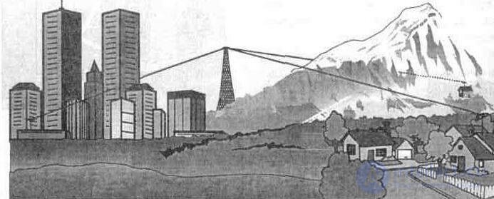
Fig. 2. 5. Distribution of television signals in the city (shadow zone)
In the presence of direct visibility between the antennas of the telecentre and the receiver, along with the direct and the waves reflected from buildings, roofs, the earth and other objects come to the point of reception (Fig. 2. 6). In cases when the transmission is carried out with vertical polarization of the waves, it is necessary to take into account that reflections are most intense from objects extended vertically - these are high-rise buildings, trees, walls of individual buildings, pipes of industrial enterprises, etc. (Fig. 2. 7)
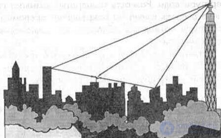
Fig. 2. 6. Distribution of television signals in the city in the presence of direct visibility.
The field strength varies greatly with changes in the height of the receiving antenna (at close distances from the transmitting antenna), as well as when the antenna is moved within the roof of the same house. In this case, the higher the frequency of the transmitted television channel, the more changes the field strength at the receiving point.
In multi-channel television broadcasting, the addition and subtraction of direct and reflected signals leads to the fact that
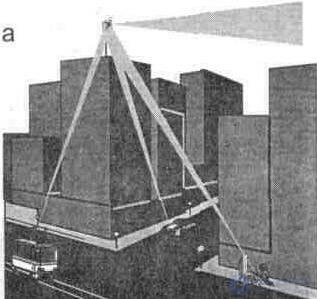
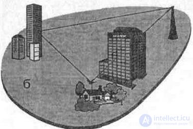
Fig. 2. 7. The effect of interference on reception:
a) industrial interference, 6) natural interference.
An antenna can increase the field strength of some television channels and weaken the field strengths of others.
Repeated images can be caused not only by the reception of the reflected signals, but also by the mismatch of the antenna and the feeder. In this case, the received signal is reflected from the TV input to the antenna, as a result of which additional repeated images appear on the screen.
In closely located multi-storey buildings from the telecentre, when the television is operated on a collective antenna, repeated images are also noticeable. At high field strengths near the transmitting antenna, due to the weak shielding of the input circuit of the TV, the external induced signal penetrates the antenna input. The transit time of the induced signal is less than the transit time of the signal received by the antenna, so on the TV screen the repeated image is reproduced to the left.
As the frequency of the television channel increases, the signal penetration increases. It is possible to eliminate or reduce the repeated image by selecting the installation location of the antenna as well as using antennas with a narrow radiation pattern and high rates of protective action factor (KZD).
In cases where it is not possible to get rid of the repeated image (the antenna is installed in places closed from a direct signal), the antenna is transferred to the nearest tall building, from the roof of which direct visibility to the transmitting antenna is provided.
2. 3. Reception quality
2. 3. 1. The parameters of television receivers, affecting the quality of reception
There is a large number of television receivers in operation - portable and stationary, domestic and foreign, having various operational and technical parameters.
As it is known, confident reception of a television signal is complicated by the presence of both industrial (industrial) interference and noise received by the antenna, and the intrinsic noise of the TV. The lower the voltage of noise and interference, the lower the required voltage signal at the input of the TV:
and the farther away from the television station is a confident reception of television programs
One of the most important parameters affecting the quality reception of television programs is the sensitivity of the television receiver. This is the lowest voltage value of the signal at its input.
necessary to ensure satisfactory image quality, sound and synchronization (image stability). Each television receiver has its own level of sensitivity, however, to ensure a high-quality image, the signal voltage should be about five times greater than that indicated in the TV passport. For color television receivers, the signal voltage must be greater than for black and white, 1, 2 ... 1, 3 times.
Чувствительность, ограниченная шумами, характеризует способность телевизора принимать слабый сигнал с учетом его собственных шумов в тракте изображения и звука. Она определяется наименьшей амплитудой сигнала на входе телевизора, при котором обеспечивается нормальное значение напряжения на катоде кинескопа при допустимом отношении сигнал/шум (20 дБ, т. е в 10 раз по напряжению). Согласно ГОСТу [2. 3] она должна составлять в /-/// диапазоне (метровые телевизионные каналы) — не более 70 мкВ (-72 дБ/мВт), в IV-V диапазоне (дециметровые телевизионные каналы) — не более 100 мкВ (-69 дБ/мВт).
Чувствительность канала изображения, ограниченная синхронизацией, определяется наименьшей амплитудой сигнала на входе телевизора, при котором еще сохраняется устойчивая синхронизация изображения (без учета его качества). В метровом диапазоне согласно ГОСТу [2. 3] она составляет не более 40 мкВ (-75 дБ/мВт), а в ДМВ диапазоне не превышает 70 мкВ (-72 дБ/мВт).
В случаях, когда телевизионный приемник эксплуатируется вблизи телевизионного центра (или ретранслятора), следует учитывать и максимально допустимый уровень входного сигнала (наибольшее напряжение высокой частоты на входе телевизионного приемника, при котором изображение и звук заметно не ухудшаются), составляющий для большинства телевизоров 87 мВ (-10 дБ/мВт).
Качество приема в значительной степени зависит и от избирательности телевизионных приемников, находящихся в эксплуатации. Избирательность характеризует способность телевизора подавлять помехи по побочным каналам приема (зеркальному, прямому и т. д.), способным вызвать искажения при приеме полезного сигнала.
В диапазоне метровых волн каналы распределены так, что ТВ передатчики соседних телецентров не создают помехи на зеркальных каналах этого диапазона.
Зеркальным каналом является полоса частот, ограниченная значениями:
fз.min=2(fн.u+fпр)*fmax (2.11) fэ.max = 2 (fн.u + fnp) - fmin (2.12)
где f н.и - частота несущей изображения канала приема;
fnp - частота промежуточной изображения (38МГц);
fmin и fmax - граничные частоты исходного канала приема, зеркальный канал которого определяется.
Однако несущие частоты передатчиков дециметрового диапазона волн, работающих на предыдущих каналах, попадают в каналы (начиная с 29-го телевизионного канала), зеркальные по отношению к другим каналам данного диапазона [2. four]. Это влияние каналов учитывается при планировании сетки частот на границах зон обслуживания ТВ
передатчиков.
В соответствии с требованиями ГОСТа [2. 3] избирательность по зеркальному каналу для / - ///диапазонов равна - 45 дБ, для IV - I/диапазонов - 30 дБ. Обеспечить высокую избирательность телевизионных приемников, в которых используются селекторы каналов с электронным управлением, весьма проблематично ввиду низкой добротности резонансных контуров, перестраиваемых варикапами.
Чем хуже параметры телевизионного приемника, тем выше требования предъявляются к выбору антенно-фидерного устройства и месту его установки для обеспечения качественного приема телепередач.
Оценить качество приема можно с помощью предложенного ниже метода.
2. 3. 2. Субъективная оценка качества принимаемого изображения.
Субъективный метод оценки качества изображения стандартизирован в документах МККР и широко используется у нас и за рубежом. Метод позволяет установить обобщенное мнение наблюдателей, привлекаемых для оценки отдельных параметров (показателей) качества изображения. В нем применяется пятибальная ('школьная') шкала оценок (табл. 2. 1), позволяющая привлекать к оценке любых наблюдателей почти без подготовки (специалистов и не специалистов). Чем больше наблюдателей участвуют в оценке качества изображения, тем выше достоверность получаемых
результатов.
Наблюдение проводится по испытательной таблице на расстоянии около шести высот экрана; регуляторы яркости и контрастности устанавливают в положения, позволяющие различать максимальное число градации яркости. При этом не должно быть прямой засветки экрана внешними источниками света.
По методике, изложенной ниже, можно с достаточной точностью можно оценить работу своего антенно-фидерного устройства и, исходя из усредненной (среднеарифметической) оценки, определить пути улучшения приема телевизионных программ. Более точные выводы можно сделать,
проведя замеры и расчеты напряженности поля в месте приема, уровня сигнала на выходе приемной антенны, затухания фидера снижения и др.
Таблица 2. 1. Оценка качества изображения
Оценка (балл) | Качество изображения | Ухудшение качества |
five | отличное | незаметно |
four | the good | заметно, но не мешает |
3 | удовлетворительное | немного мешает |
2 | неудовлетворительное | мешает |
one | непригодное | сильно мешает |
Для оценки качества работы антенно-фидерного устройства (предполагается, что телевизионный приемник эталонного качества)
перед наблюдателями ставится задача — определить наличие помех, шумов, повторов и искажений изображения (табл. 2. 2) при приеме тестовой таблицы или качественной передачи.
Каждый наблюдатель по-своему характеризует визуальный эффект помех на изображении. При этом обычно дают такие оценки, как рябь на изображении", "мелкие и крупные зерна", "хлопья" и т. д. Для единообразия оценки результатов предлагаются следующие определения:
наличие помех — на экране наблюдаются паразитные узоры (сетка) или периодические нарушения синхронизации (подергивание строк или кадров), вызванные работой различного рода электрических устройств и мешающих радиостанций;
наличие шумов — появление на экране беспорядочной засветки в виде мерцающих точек (''снега'');
повторы изображения — появление на экране повторного изображения справа (иногда слева} от основного;
искажения изображения — снижение четкости изображения, нарушение правильности передачи оттенков яркости, переконтрастность, смещение отдельных элементов изображения.
Таблица 2. 2. Оценка качества работы антенно-фидерного устройств.
оценка, баллы | Показатель качества изображения |
Наличие п о м е х | |
five | Помехи совершенно не наблюдаются |
four | Помехи заметны только при тщательном рассмотрении с близкого расстояния |
3 | Помехи заметны и временами отвлекают от просмотра передач |
2 | Помехи очень заметны и мешают просмотру изображения |
one | Наличие помех исключает возможность просмотра изображения, изображение покрыто сеткой, синхронизация нарушается |
Наличие шумов | |
five | Шумы не наблюдаются |
four | Шумы наблюдаются при рассмотрении с близкого расстояния |
3 | Шумы незначительны и практически не мешают просмотру изображения |
2 | Шумы значительны и мешают просмотру изображения |
one | Изображение покрыто сплошным «снегом», просмотр затруднен |
Повторы изображения | |
five | Повторное изображение незаметно |
four | Повторное изображение малозаметно и просматривается при тщательном рассмотрении с близкого расстояния |
3 | Повторное изображение заметно, но не ухудшает общей видимости |
2 | Повторное изображение сильно просматриваться и ухудшает качество изображения |
one | Наличие сильных повторных изображений лишает возможности нормального восприятия изображения |
Искажения изображения | |
five | Изображение полностью соответствует передаваемому сюжету |
four | Искажения малозаметны и не влияют на качество изображения |
3 | Искажения заметны и незначительно влияют на качество изображения, ухудшая общую видимость |
2 | Искажения сильно заметны и затрудняют просмотр изображения |
one | Искривление вертикальных линий (изломы изображения), срыв синхронизации, просмотр изображения невозможен |
В качестве примера дается оценка качества работы антенно-фидерного устройства при приеме девяти программ, для удобства результаты оценок сведены в табл. 2. 3.
Таблица 2. 3. Результаты оценок качества приема
Показатель качества изображения | Диапазон вещания | ||||||||
II | III | IV | |||||||
Телевизионные каналы | |||||||||
four | 6 | eight | ten | 12 | 22 | 28 | thirty | 33 | |
Наличие помех | four | five | four | 3 | four | 3 | four | 3 | four |
Наличие шумов | 2 | five | four | 3 | four | 3 | 3 | 3 | four |
Повторы изображен. | 2 | four | four | 3 | four | 3 | four | four | four |
Искажения изображен. | four | four | four | four | four | 3 | four | 3 | four |
Среднеарифметическая оценка | |||||||||
- канала | 3 | 4, 5 4 | 3, 3 | four | 3 | 3, 8 | 3, 3 | four | |
- диапазона | 3 | 3, 93 | 3, 5 | ||||||
Общая оценка работы антенно-фидерного устройства = 3, 6 | |||||||||
По результатам наблюдений выведены среднеарифметические оценки по показателям для каждого из проверяемых каналов (трансляция которых осуществляется в данной местности) и общая оценка работы антенно-фидерного устройства. В этом примере антенно-фидерное устройство (применялись две антенны - III и IV диапазонов) работает удовлетворительно — на 3, 6 балла. При рассмотрении результатов оценок по каналам приема, можно сделать следующие выводы:
- хуже всего осуществляется прием каналов 4, 10, 22, 30;
- из-за значительных шумов и повторных изображений, свидетельствующих о недостаточном усилении, необходима установка дополнительной антенны и ориентировка ее в пространстве (для уменьшения повторных изображений) для приема сигналов во II диапазоне (4 канал);
- также необходимо повысить величину сигнала при приеме каналов IV дециметрового диапазона волн (возможно установить антенный усилитель);
- для улучшения качества приема в III диапазоне (10 канал) - надо изменить высоту установки антенны так, чтобы найти максимум напряженности поля для этого телевизионного канала.
Для более полноценных выводов необходимо учитывать условия распространения и приема радиоволн в данной местности.
2.4. Рекомендации по выбору антенн
При выборе телевизионной антенны всегда возникают трудности, и не только у радиолюбителей, но и у специалистов. Антенну, которая способна принять все передаваемые программы с достаточным качеством, подобрать очень сложно. Здесь без предварительной оценки условий приема однозначный ответ дать невозможно.
Для этого прежде всего небходимо знать номера телевизионных каналов (либо канал), которые необходимо принять в данной местности, а также диапазоны телевизионного вещания, в которых эти каналы находятся, и их частоты (табл. 1.2). После чего можно определить коэффициент перекрытия по частоте (Kf) принимаемых каналов:
К1 = fmax/fmin (2.13)
где frnax - верхняя частота высшего (номера) канала;
fmin - нижняя частота низшего (номера) канала.
Если результаты вычислений находятся в пределах:
1,01... 1,16, то для приема используется канальная антенна;
1, 16... 1,3 - многоканальная антенна;
1,3... 19,0 - диапазонная антенна,
Now, knowing the operating frequency range and the overlap factor, it is possible to preselect the antenna.
EXAMPLE 1: Reception is conducted on television channels 4, 6, 8, 10, 12, 22, 28, 30, 33 (the bands II, III and IV overlap). Determine the overall overlap ratio from 4 to 33 channel.
K1 = 574/84 = 6.8.
The overlap coefficient for each range was:
K2 = 92/84 = 1.09.
K3 = 230/174 = 1.32.
K4 = 574/478 = 1.2.
Based on the result obtained, a wideband antenna would have to be used to receive all channels. However, such antennas do not have the necessary parameters for satisfactory reception, or they are complex in design (combined antennas). Therefore, in this case, it is advisable to use three antennas:
- for reception in the II range (4 TV channel) - channel antenna;
- in the III range (6 ... 12 channel) -band;
- in the IV range (22 ... 33 channel) - multichannel or band. To select a specific type of antenna, use the table. 2. 4, where Gav is the gain relative to an isotropic antenna, O is the width of the radiation pattern in the horizontal plane.
Table 2. 4. Typical antenna parameters.
Antenna | Range | Reception channels (frequency) * | Gcp, db | KZD, - (DB) | about. hail. |
channel | |||||
Half Wave Vibrator | I, II, III | 1.2 ... 12 | 2.15 | 0 | 2x90 |
"Wave channel" | |||||
3-element | I | 1.2 | five | 12 | 70 |
4-element | II | 3,4.5 | 7 | 12 | 70 |
5-element | II | 3,4.5 | eight | 14 | 60 |
11-element | III | 6,7-12 | 10.5-11.5 | 23 | 40-45 |
18-element | IV | 21.22-34 | 14 | 22 | 38 |
V | 35, 36 - 60 | ||||
21-element | IV | 21, 22-34 | 17 | 28 | 18 |
V | 35, 36 - 60 | ||||
27-element | IV | 21.22-34 | nineteen | 28 | 17 |
V | 35, 36 - 60 | ||||
Continued table. 2.4
Antenna | TV range | Reception channels (frequency) * | Gcp, db | KZD, - (DB) | about, hail. |
multichannel * | |||||
Half Wave Vibrator | III | 6-7, 8-9, 10-12 | 2.15 | 0 | 2x90 |
"Wave channel" | |||||
4-element | I. II | 1-3, 2 - 3 | 6.5 | 14 | 68 |
5-element | I, II | 1-3, 1- 4. 2-5, 3-5 | 7.5 | 14 | 65 |
5-element | III | 6-7, 7-8, 9-11, 11-12 | 7 | 14 | 58 |
11-element | III | 6-7, 7-8, | |||
9-11, 11-12 | 11.5 | 23 | 42 | ||
5-element | IV | 21-28, 25-34 | 6-8 | 18 | 54 |
10-element | Iv, | 21-30 | 8-11 | 21 | 38-40 |
V | 38-50 | ||||
16-element | IV | 27 -39 | 12 - 14 | 22 | 35 |
V | 31 -50 | ||||
21st element | IV | 31 -50 | 14 - 17 | 18 | 21 |
V | 41-60 | ||||
range | |||||
"Wave channel" | |||||
6-element | l-ll | 15 | 8.5 | sixteen | 55 |
7-element | III | 6-12 | eight | 9-12 | 45-55 |
10 element | IV | 21 -40 | 8-11 | 21-22 | 38-40 |
V | 41 -60 | ||||
15-element | IV | 21 -39 | 9-12 | 14-24 | 32-46 |
16-element | IV-V | 21 -60 | 10-13 | 22 | 35 |
21-element | IV-V | 21 -60 | 14 - 18 | 28 | 18 |
27-element | IV | 21 -35 | 17 - 19 | 28 | 18 |
v | 36-55 | ||||
Zigzag | III | 6-12 | 6.5-7 | eight | 2x90 |
Zigzag with reflector | III, | 6-12 | 8-10 | 15-26 | 55 |
Iv, | 21 -35 | ||||
V | 36-60 | ||||
Logperiodic | IV-V | 21 -60 | 8.5 | 18 | 45-55 |
LUCH-1 | l-lll | 1 -12 | 2.5 | eight | 2x90 |
WAVE-1 | l-lll | 1 - 12 | 4-5 | 10-14 | 110 |
Fan (TAI-12) | l-lll | 1 - 12 | 2-3,5 | eight | 2x90 |
Framework | l-ll | 15 | 8-11 | 15 | 55-70 |
III | 6-12 | ||||
IV | 21 -39 | ||||
V | 40-60 | ||||
* - the bandwidth of these antennas may differ from those shown in the table.
In our case, fit:
- to receive 4 channels 4-or 5-element antenna "wave channel";
- to receive 6-12 channels 7-element antenna "wave channel", or zigzag, or frame;
- for receiving 22 - 33 channels 10 - 21-element wave antenna
channel ", or frame, or log-periodic.
In order to evaluate the amplification properties of preselected antennas, it is necessary to know the field strength at the installation site of the receiving antenna. Exact results can be obtained by applying special measuring equipment, however, for the vast majority of radio amateurs and specialists this is not available.
A rough estimate of the field strength is possible by calculating its value using formula 2. 10 for the weakest receiving channel in each range. In our case, this is 4 channel of the II range (Lср = 3.41 m), 10 channel of the III range ( Lcp = 1.43 m) and 30 channel of the IV range (Lcp = 0.549 m). To simplify the calculations, we take the effective radiated power of the station Рc = 1 kW, the height of the transmitting antenna H = 150 m, receiving h = 10 m, distance between the antennas R = 30 km.
First, substituting the original data in formula 2.1, we find the distance of visibility:
g = 4.12 (150 ^ 0.5 + 10 ^ 0.5) = 63.5 km
Calculating the relationship
R / r = 30 / 63.5 = 0.47 and (h / H) ^ 0.5 = (10/150) ^ 0.5 = 0.3,
from the graph (Fig. 2.3, ) we find the correction coefficient m = 0.63. We determine the validity of inequalities 2.7 and 2.8, for the selected by us 4.10 and 30 channels, respectively:
R = 30 km <0.8 r = 0.8 * 63.5 = 50.8 km 150 * 10 * 0.63 / 30000 * 3.41 = 0.009, i.e. less than 0.1. 150 * 10 * 0.63 / 30000 * 1.43 = 0.022, i.e. less than 0.1. 150 * 10 * 0.63 / 30000 * 0.54 = 0.058, i.e. less than 0.1.
Since inequalities 2.7 and 2.8 are satisfied, then substituting the values in formula 2.10, we calculate the field strength at the receiving point:
E4 = (2,18 • 0,63 • 150 • 10 • 1 ^ 0.5) / 3,41 • 900 = 0,671 mV / m E10 = (2,18 • 0,63 • 150 • 10 • 1 ^ 0.5) / 1.43 • 900 = 1.600 mV / m
Ezo = (2,18 • 0,63 • 150 • 10 • 1 ^ 0.5) / 0,54 • 900 = 4,238 mV / m
Compare the readings with the table. 1.3, we note that the calculated values of the field strength for a distance of R = 30 km exceed the minimum allowable table values necessary for satisfactory reception. Therefore, comparing the gains of pre-selected antennas (Table 2.4) and the recommended values of antenna gains given in Table. 1.3 (p. 10), we can conclude:
- to receive signals on TV channel 4, it is enough to use a 4-element antenna “wave channel”;
- for receiving signals on 6-12 channels it is possible to use any of the band antennas intended for reception in the III range;
- A 10-element wave channel antenna will be suitable for receiving signals on channels 22-33.
To clarify the gain, use the formula 3.11 table. 3.5. To do this, without taking into account the loss in the feeder, it is necessary to substitute the field strength values and the permissible signal voltages at the input of the television receiver into this formula.
Table 2.5. The required signal strength at the input of the television receiver.
frequency range | U, µV | |
Black and white | Color | |
I | 360 | 468 |
II | 290 | 377 |
III | 250 | 325 |
IV, V | 310 | 403 |
Determine the effective length of the antennas of the calculated channels that are at a distance from the transmitting antenna R = ZOkm, for receiving broadcasts by a color television receiver:
l4 = 377/671 = 0.561 m l10 = 325/1600 = 0.203m l30 = 403/4238 = 0.095 m
Calculate the efficiency of the feeder reduction. In this case, we use a coaxial cable RK-75-4-13 with the minimum required length l = 15m. From tab. 6.3 we determine the attenuation coefficient in = 0.13 dB / m for the frequency f = 1OOMHz. Using the formula 6.27, we calculate the attenuation of the reduction feeder for these reception channels, in our case for the frequencies fcp4 = 88 MHz, fcp10 = 210 MHz, fcrzo = 548 MHz:
B4 = B '• (f4 / f') ^ 0.5 = 0.12 B10 = B '• (f10 / f') ^ 0.5 = 0.19 B30 = B '(f30 / f') ^ 0.5 = 0.3 .
Using the calculated values в4, в10, в30, we determine the efficiency of the feeder reduction by the formula 6.21
n = 10 ^ (gl / 10) n4 = 0.66; n10 = 0.52; n30 = 0.35.
Using the formulas 3.12 and 3.14, we determine the gain of the receiving antenna taking into account the efficiency of the feeder reduction ln
Gn = (ln / 0,16L) ^ 2 / n (2.14)
where l n - the effective length for the calculated channel;
L is the wavelength of the calculated channel;
n - the efficiency of the feeder reduction.
G4 = (0.561 / 0.16 · 3.41) ^ 2 / 0.66 = 1.6 G10 = (0.203 / 0.16 • 1.43) ^ 2 / 0.52 = 1.5 G30 = (0 , 95 / 0.16 • 0.54) ^ 2 / 0.35 = 3.45.
The resulting values in times translate into decibels (Appendix 3, or by the formula 3.4) and obtain the following values:
G4 = 4.08 dB G10 = 3.52 dB G30 = 10.75 dB
The data obtained during the calculations allow you to select a specific type of antenna from Table 2.4 or Appendix 5.
EXAMPLE 2: In case the television receiver is located at a distance of P = 35km, then to determine the field strengths, effective lengths and gains of the receiving antennas, we perform a similar calculation.
Let the visibility distance be r = 63.5 km, then R / r = 35 / 63.5 = 0.55; (h / H) ^ 0.5 = (10/150) ^ 0.5 <0.3.
From the graph (Fig.2.3,) m = 0.54.
With an increase in the distance of 5 km, the field strengths decreased, but in the 11-111 ranges they still correspond to the recommendations in Table. 1.3, and in the IV range, the field strength level is less than the required. Making calculations for R = 35 km, we find the values of the antenna gains at the receiving point:
E4 = (2.18 * 0.54 * 150 * 10 * 1 ^ 0.5) / 3.41 • 1225 = 0.422 mV;
E10 = (2.18 * 0.54 * 150 * 10 • 1 ^ 0.5) / 1.43 • 1225 = 1.008 mV;
E30 = (2.18 * 0.54 * 150 * 10 * 1 ^ 0.5) / 0.54 • 1225 = 2.699 mV.
From here the effective length of the antennas will be respectively equal to:
l4 = 377/671 = 0.561;
l10 = 325/1600 = 0.203;
l30 = 403/4238 = 0.095.
Determine the gain of the receiving antennas at the previously obtained attenuation coefficients and the efficiency of the feeder:
G4 = (0.687 / 0.16 * 3.4.1) ^ 2 / 0.66 = 2.4;
G10 = (0.248 / 0.16 · 1.43) ^ 2 / 0.52 = 2.26;
C30 = (0.116 / 0.16. 0.54) ^ 2 / 0.35 = 5.15.
The resulting values in times translate into decibels (see Appendix 3) and we obtain the following values:
G4 = 7.6 dB; G10 = 7.08 dB; C30 = 14.23 dB.
The data obtained during the calculations allow you to select a specific type of antenna (with a distance of 35 km from the transmitting center) from the table. 2.4 or applications 5.
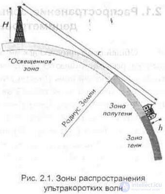
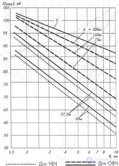
The calculation of the field strength according to the formulas is a laborious process, and in some cases is impossible at all. Therefore, in practice, to determine the field strength, graphs and tables are widely used, which are constructed taking into account the results of numerous measurements performed in real conditions. The calculations are conveniently carried out in decibels relative to the reference level, which is usually taken as 1 µV / m. Due to the inconstancy of the field in time, especially at large distances, an average level is used to characterize it, which is called the median value of the received signal level Emed. This level can be roughly estimated from the dependences of the median value (distribution curves of the CCIR) field strength on the distance:
- at distances less than 10 km - according to fig. 2.8;
- at distances over 10 km, - according to fig. 2.9 for I-III range and in fig. 2.10 for the IV-V ranges [2.6].
Fig.2.8. VHF and UHF propagation curves
Currently, there are many television stations transmitting several programs on different frequency channels. To receive them, you can use broadband antennas (log-periodic, etc.), providing reception in several bands. However, these antennas can be used only with a sufficient amount of the received signal. If the magnitude of the signal at the receiving point is small, then using such antennas requires the installation of an antenna amplifier to increase the signal-to-noise ratio at the input of the television receiver.
The use of an antenna amplifier is also desirable in cases where the television receiver does not have an adequate margin of gain. In this case, it is possible to obtain a noticeable improvement in the quality of reception, primarily on low-class television receivers.
Install the antenna amplifier is most appropriate in the immediate vicinity of the antenna (or directly on it),
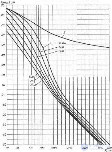
Fig. 2. 9. VHF propagation curves (I-III range)
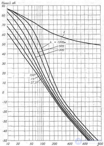
Fig. 2. 10. Curves propagation UHF (IV - V range)
which will reduce the feeder losses, and with a sufficient signal, connect several TVs to one antenna.
In addition to the typical antennas for receiving multi-channel television, active and combined (combined) antennas, described in sec. 3. By design, combined antennas combine the same or different types of antennas in the same or in several planes (for receiving waves of different polarizations).
At short distances from the television center (up to 10 km), simple antennas are used, as a rule. With increasing distance (10 ... 30 km) you can use antennas with the gain recommended in Table. 1. 3. At a considerable distance, it is necessary to use high-performance (with a narrow radiation pattern) with a high antenna gain (multi-element).
Professionals and radio amateurs know that multi-storey antennas with high gain are most effective for receiving signals in areas remote from the telecentre. However, the installation of such a system of antennas requires experience and expertise. The practical implementation of long-range reception can be carried out by a multi-element antenna of the appropriate range, or by a channel antenna (see Table 2. 4 or Appendix 5} using an additional amplifier.
If the transmitting centers are located in different directions (at significant distances), when switching from receiving one program to another, the antenna has to be reoriented, which creates considerable inconvenience. In such cases, good results are obtained when using several narrow-band high-performance antennas aimed at different transmitting centers and coordinated with the help of special matching devices.
It must be remembered that the antenna must be installed so that it ensures maximum reception of the useful signal from the television center and weakens the effect of interference as much as possible.
The description of industrial antennas is given in Sec. 3, and antenna amplifiers - Sec. 4 and 5.

Comments
To leave a comment
Television and antennas. Theory. Broadcast and cable. Digital and analog
Terms: Television and antennas. Theory. Broadcast and cable. Digital and analog