Lecture
Devices designed to transmit high-frequency energy received by the antenna to a television receiver are called transmission lines. The main task of the transmission line (feeder) is the transmission of electromagnetic energy from a TV antenna to a TV set with minimal signal loss. The quality of the received image depends on the correctness of the execution of the feeder line, its coordination with the antenna and the TV. The word "feeder" comes from the English "to feed" - to feed.
There are several types of high-frequency power transmission lines. To perform interfloor or inter-row connections in complex common-mode antennas, two-wire overhead lines are used (Fig. 6.1.).
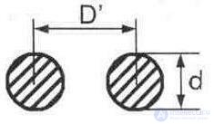
Fig. 6.1. Cross-section of a two-wire unshielded line of round wires
The range of the wave resistance of these lines can be quite wide. Both wires of the air symmetric line must be strictly symmetrical with respect to each other and the ground, which is its disadvantage, since it is practically difficult to maintain the same distance between the wires throughout the length of the line, as well as between each wire and ground. The characteristic impedance for the line of circular wires depends on the ratio of the distance between the two conductors to their diameter, and is determined by the formula

The formula is valid for b> 3a and d << a,
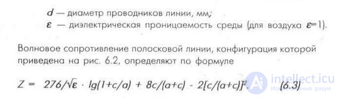
where Z is the wave resistance of the strip line, Ohm;
e is the dielectric constant of the medium;
a is the width of the strip line;
c is the distance between the strip lines (or the thickness of the dielectric);
b is the dielectric width;
d is the thickness of the strip conductor.
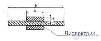
Fig. 6.2. Schematic representation of the strip line
The dependence of the wave resistance of strip lines on its geometrical dimensions is shown in Fig.6.3.
Asymmetrical air rigid lines are used for the manufacture of matching transformers, filters, branch pipes, etc. The air coaxial line is shown in Fig. 6.4 [6.2].
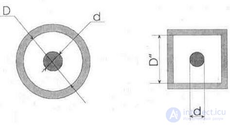
Fig. 6.4. Constructive options of hard air lines:
a - concentric (coaxial) line, b - cylindrical conductor in a square tube.
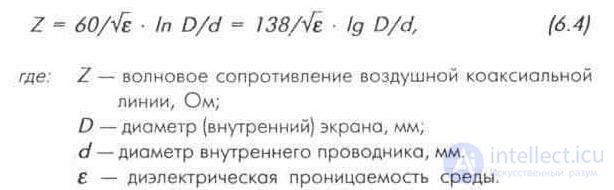
Wave resistance of the air coaxial line is determined by the formula
The characteristic impedance of the line shown in Figure 6.4.6 is determined by the formula
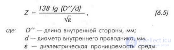
The advantage of overhead lines is the possibility of receiving. wide range of wave impedances. For practical purposes, in their manufacture, you can use the diagram in Figure 6.5 [6.1].
The graph for comparison shows the dependence of the wave resistance of overhead lines and shielded lines with a solid dielectric (polyethylene insulation, e = 2,3).
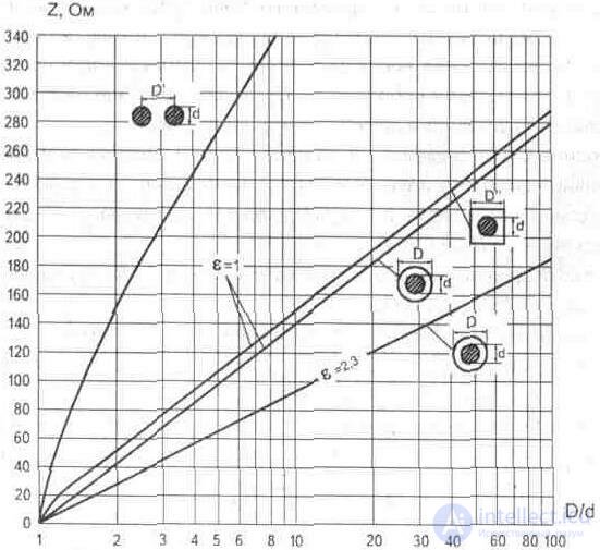
Fig. 6.5. Air line wave impedance diagram
The transmission line, the length of which is comparable with the wavelength of electromagnetic oscillations propagating in it (l = ldl.vol), and the distance between its conductors is significantly less than a quarter of the wavelength, is called the long line.
With an ideal matching of the line with the load, when the line is loaded on a purely active and equal to the wave resistance (Zn = R = Zb), only incident waves [waves propagating along the line from the generator to the load} exist in the line . The voltage and current along the transmission line have the same value, and the phases of the wave are different. The absence of reflected waves is explained by the fact that all the energy supplied by the incident waves is absorbed by the load (dissipated on it}. This line is called coordinated with the load, and the mode in the line is called the traveling wave mode.
If the line is open (Zn = infinity, short-circuited (Zn = O) or
Since the load has a pronounced reactive nature (Zn = jXn), then the load Zn does not absorb energy, but fully reflects it back to the signal source ( generator). Such a mode in the line is characterized by the interference of the incident and reflected waves. Reflected waves, adding to the incident, create the so-called standing waves. In this case, there are some points on the line where the voltage is always zero: these are voltage nodes. The points where amplitude voltage is maximal are called “antinodes” of voltage.
The input impedances of a short-circuited and open-loop line are reactive in nature and vary with the length of the line, and at points that are multiples of a quarter of the wavelength (l = n * ldvv / 4), the input resistance is active and
has the value Z = 0 or Z = infinity.
Segments of long lines whose length is a multiple of a quarter wavelength are called RESONANT.
In radio engineering, the property of segments of a long line to resonate at certain frequencies is widely used. The geometric length of the line can be reduced by connecting the capacitor to its open ends (Fig.6.6). The inclusion of a variable capacitor (varicap) allows you to adjust the length of the long line (oscillating circuit with distributed parameters) to the desired wavelength.
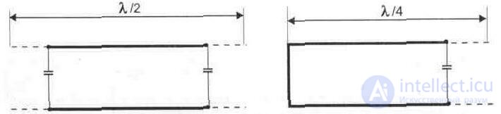
Fig. 6.6. Reducing the geometric length of the line
Segments of long lines (closed or open at the end} are used as filter elements of the resonant circuits of high-frequency blocks, loops for tuning antennas, etc.) The magnitude and nature of the input resistance of the open (Fig. 6.7) and the closed line (Fig. 6.8) change to depending on how many waves fit along the line.

If the line load is not equal to the line impedance, then the line mode is characterized by the simultaneous existence of standing and traveling waves. This mode in the line is called MIXED. In such lines there are no nodes and antinodes of voltage and current, but there are maxima and minima of voltage and current. Evaluation of the mode of operation of the line is characterized by the coefficient of the traveling wave:
KBV = Umin / Umax (6.6)
where Umin is the amplitude at the voltage node. AT;
Umax, - amplitude in voltage antinodes, V.
The traveling wave coefficient can be determined from the relations:
K = R / Z with R Z (6.7)
where Z is the characteristic impedance of the line;
R is the line load resistance.
Consequently, this coefficient characterizes the degree of matching the line with the load. When R = Z, it is equal to one, which means complete alignment of the line with the load, at which the traveling wave mode will be in the line.
In reality, such lines do not exist due to the impossibility of perfect matching of the load with the line.
The inverse of the traveling-wave coefficient is called the STANDING WAVE FACTOR:
SWR = 1 / IPA. (6.8)
The ratio of the amplitudes of the voltage of the reflected and incident waves
is called the reflection coefficient, which is determined from the formulas:
p = (1 -KBV) / (1 + KBV) or (6.9) p = (KSV- 1) / (KSV + 1). (6.10)
The amplitudes of the voltages of the incident and reflected waves are measured using directional couplers.
The main parameters of the transmission line are the impedance, linear capacitance, specific attenuation.
WAVE RESISTANCE OF THE LINE (Z) is the ratio of the complex voltage amplitudes to the current of the incident or reflected waves. It is complex in nature and is related to the linear inductance Lo and the linear capacitance of the line Co as follows:

For coaxial cables, Lo and Co are determined by the formulas:

where D is the diameter [internal) of the screen, mm;
d is the diameter of the inner conductor, mm.
Cable running capacity is the capacity of a unit of cable length. Usually the linear capacitance of the cable is indicated in pf / m:

where e is the dielectric constant of the insulation;
D - diameter (internal) of the screen, mm;
d is the diameter of the inner conductor, mm.
The values of the dielectric constant e of materials are given in Appendix 9.
The characteristic impedance of a coaxial cable is determined by the geometric dimensions of its cross section and dielectric constant [see formula 6.4).
An electromagnetic wave in a feeder line with a dielectric propagates with a lower speed than in free space (for vacuum, e = 8.854 * 10 ^ (- 12) ). So, in an air line, the wave propagation speed is only 2-3% less than in free space, and in a cable line filled with a dielectric, the speed depends on the dielectric constant of the filling material,
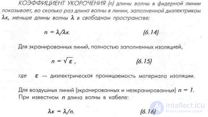
In foreign reference books, instead of the wavelength shortening factor, the DEADLINE TRANSMISSION LINKING RATE is given, (k = 1 / s). Radio waves in free space propagate at the speed of light (c = 3 * 10 ^ 8 m / s). In the transmission line, their speed decreases by a factor of k. The values of k vary with the design of the line.
A typical value of k is:
0.75 for a two-wire line with plastic insulation;
0.67 - for coaxial line with solid plastic insulation;
0.85 for air-insulated coaxial line;
0.97 - for open two-wire overhead line. Due to losses, the electromagnetic wave, propagating along the line, decreases in magnitude - decays. The efficiency of the signal passing through the line (feeder) is determined by the value of the specific attenuation (P). DRIVE DROP is characterized by a decrease in the signal voltage as it propagates along a line at a working frequency per unit cable length. Express attenuation in decibels per meter (or neper per kilometer).
If it is necessary to convert attenuation units, you can use the following relation: 1 dB = 0.115 nep (or 1 nne = 8.686 dV).
The specific attenuation depends on the materials from which the conductors and insulation are made, their transverse dimensions, the measurement frequency and is determined by the formula
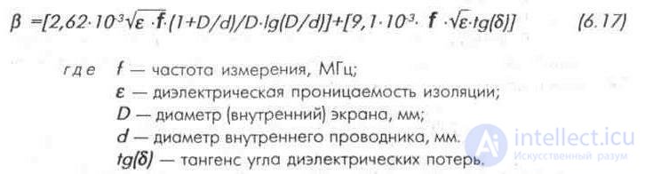
The higher the frequency and the longer the cable, the greater the attenuation of the P feeder line.
EXAMPLE: Determine the total attenuation of a feeder line made of a coaxial cable RK-75-4-11 with a length l = 25 m for a V-TB channel. From tab. 1.2 we find the frequency of the V-TB channel: Fcp = 96 MHz. According to the table. 6.3 we determine the attenuation of the cable at this frequency in = 0.1 dB / m. The total attenuation will be T = c * l; T = 0.1 * 25 = 2.5 dB
The decrease in the voltage of the signal, as it propagates along the line, occurs exponentially:
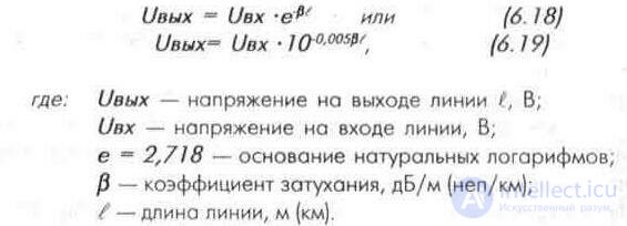
The attenuation of the signal power in the feeder line is determined by the formula
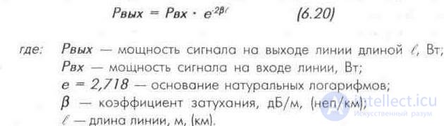
THE FACTORY OF USEFUL ACTION of a line is defined as the ratio of the power at the output of the line to the power at its input:
It follows from the formula that the smaller the line attenuation coefficient and the shorter its length, the greater the efficiency.
RD - symmetric radio frequency cables, two-core or two coaxial pairs;
PC - RF cables with coiled conductors coaxial and symmetrical.
According to the constructive implementation of the isolation, the radio frequency cables are divided into three groups:
- cables with solid insulation, in which the entire space between the inner and outer conductors (coaxial cables) or between the conductors and their shield (symmetrical cables) is filled with solid insulation or winding of insulating tapes;
- air-insulated cables, which have an internal conductor (coaxial cables or symmetrical cables of two coaxial pairs) or conductors (symmetrical cables) at a certain interval there are washers made of an insulating material, caps or a cord, superimposed on a spiral coil, forming insulating the frame between the inner and outer conductors or between the conductors and their screen;
- semi-air insulated cables, in which a tube of insulating material, made solid or in the form of tape winding, is placed on top of or under the insulating frame placed between the inner and outer conductors (coaxial cables or symmetrical cables of two coaxial pairs) or on each of two cores (balanced cables). The semi-air insulation also includes porous-plastic, balloon and insulation in the form of a slotted tube.
According to the nominal characteristic impedance, the following cable rows are installed:
- for type RK- 50, 75, 100, 150 and 200 Ohms;
- for type PC- 50, 75, 100, 150, 200, 400, 800, 1600 and 3200 Ohm;
- for type RD - 75, 100, 150, 200 and 300 ohms. Coaxial cables, depending on the nominal diameter of insulation, are divided into four groups:
- subminiature - with a diameter up to 7 mm;
- miniature - from 1.5 to 2.95 (3.0) mm;
- medium size - from 3.7 to 11.5 mm;
- large - more than 11.5 mm.
For heat resistance cables are divided into three categories:
- conventional heat resistance - for temperatures up to 125 ° C inclusive;
- increased heat resistance - from 125 to 250 ° C inclusive;
- high heat resistance - above 250 ° С.
Each cable is assigned a symbol (cable mark), which consists of letters indicating the type of cable and three numbers (separated by dashes).
FIRST NUMBER means the value of the nominal wave resistance.
SECOND NUMBER means:
- for coaxial cables - the insulation diameter, rounded for diameters greater than 2 mm to the nearest integer.
- for cables with spiral inner conductors - the value of the nominal diameter of the core;
- for balanced cables with two coaxial pairs - the value of the diameter of the insulation of the coaxial pair, rounded the same way as for coaxial cables;
- for balanced cables with insulated conductors - the value of the largest diameter by filling or by twisting.
The THIRD number is a two- or three-digit number, the first digit of which means the insulation group and the heat resistance category of the cable, and the subsequent number is the sequence number of the cable design.
Table b. one
|
Numerical value |
Insulation grouping (according to GOST 11326.0.71) |
Insulation material (according to GOST 11326.0-67) |
|
one |
Solid insulation of conventional heat resistance (up to 125 ° C) |
Polyethylene of various modifications and its mixtures |
|
2 |
Solid insulation of high heat resistance (125-250С) |
Fluorone (fluoroplast) and its copolymers |
|
3 |
Semi-air insulation of conventional heat resistance (up to 125 ° C) |
Polystyrene (Styroflex) |
|
four |
Semi-air insulation of high heat resistance (125-250С) |
Polypropylene and its mixtures |
|
five |
Air insulation conventional heat resistance (up to 125 ° C) |
Rubber |
|
6 |
Air insulation of high heat resistance (125-250С) |
Inorganic insulation |
|
7 |
Air insulation of high heat resistance (above 250С) |
|
Each insulation group, with the appropriate heat resistance of the cable, is assigned the following numerical designation (Table 6.1).
The letter C is added to the cable mark of increased homogeneity or increased stability of parameters at the end of the dash . Limit deviations from nominal values of wave resistance for 75-ohm coaxial cables of increased homogeneity, with an insulation diameter of 3.7 - 9.0 mm, are:
- at continuous isolation ± 1,5 Ohm,
- with semi-air or air insulation ± 2 ohms.
In the designation of cables intended for systems of collective reception of television and individual receiving antennas, the letter A is added (RC-75-4-11A). These cables differ from the main brands of external conductor, performed by the density of 40-60% [at the angle of the overlay braid 65-74). Cables for television antennas are not subjected to a crown test and do not measure attenuation at 3 GHz before and after the stability test.
The symbol of the RF coaxial cable RK-75-4-12 means:
RK - RF cable;
75 - characteristic impedance. Ohm;
4 - insulation cable diameter, mm;
12 is a two-digit number in which the first digit indicates the type of insulation (1 is continuous insulation of conventional heat resistance up to 125 ° C), and the second is ordinal
cable design number.
On the polyethylene sheath or on the sheath of polyvinyl chloride plasticad along the entire length of the cable with an outer diameter of more than 4 mm at a distance of not more than 1 m from each other are usually applied:
- cable brand;
- the trademark of the manufacturer or its symbol;
- the year of the cable.
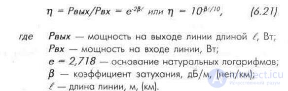
Shielded unbalanced (coaxial) cable RK (Fig.6.9.a) and unscreened symmetric ribbon cable CATV [TV antenna cable with vinyl insulation) - Fig. 6.9.v. In some cases, use symmetrical shielded cables brands RD (Fig. 6.9.d) and aerial two-wire balanced lines.
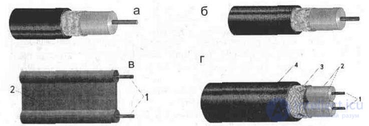
Fig. 6.9. RF cable designs:
a - asymmetrical coaxial with a single internal wire;
б — несимметричный коаксиальный с многожильным внутренним проводом;
в —симметричный ленточный КАТВ; г— симметричный экранированный кабель РД.
Распространенной конструкцией внутреннего проводника радиочастотных кабелей является одиночный провод. Выполнение внутренней жилы в виде набора скрученных проводов (7, 19 или 37) обеспечивает эластичность, повышает гибкость и его вибрационную стойкость, (рис. 6.9.6)
Внутренний проводник радиочастотных кабелей повышенной стабильности (для работы при 200 С и выше) изготавливают из посеребренной медной проволоки. Малогабаритные радиочастотные кабели для повышения механической прочности изготовляют с внутренним проводником из биметаллической проволоки (сталь-медь).
При использовании радиочастотных кабелей в условиях высоких температур (200-300°С) в качестве экрана используют посеребренную медную проволоку, а для работы при температурах 350-450°С — никелированную медную проволоку или проволоку из нержавеющей стали.
В условиях повышенной влажности для кабелей с резиновой изоляцией экран изготовляют из луженой медной проволоки.
Конструктивно симметричный ленточный кабель КАТВ [рис.6.9.в] состоит из двух семижильных проводников 1, запресованных в полихлорвиниловый пластикат 2. При распространении сигнала по неэкранированной симметричной линии, выполненной из кабеля КАТВ, часть сигнала рассеивается в пространстве, а сама линия довольно чувствительна к сигналам помех. Для того чтобы кабель КАТВ не работал как антенна (в близких зонах от ТВ прередающих центров}, его рекомендуют скручивать (до четырех скруток на один метр).
Более защищен от помех симметричный экранированный кабель РД (рис. 6.9. г). Внутренние проводники 1 выполнены из одной либо семи скрученных медных жил. Проводники жил помещены в изоляцию 2. Поверх изоляции наложен экран 3 и защитная оболочка 4. Благодаря его экранирующим свойствам повышается помехоустойчивость приема, устраняются искажения диаграммы направленности антенны, связанные с антенным эффектом [излучением кабеля).
В настоящее время на мировом рынке имеются радиочастотные кабели различных типов (рис.6.10). Структура условных обозначений их различна и может устанавливаться фирмами-изготовителями. Так, тип кабеля, изготовляемого странами Юго-Восточной Азии, имеет следующую маркировку:
ПЕРВЫЙ ЭЛЕМЕНТ (цифра) означает округленный диаметр
кабеля по металлической оплетке;
ВТОРОЙ ЭЛЕМЕНТ (буква) означает волновое сопротивление («D» - 50 Ом, «С» - 75 Ом);
ТРЕТИЙ ЭЛЕМЕНТ (несколько ЦИФР и БУКВ через дефис)
означает тип изоляции («2V» — изоляция из сплошного полиэтилена).
Маркировка зарубежных кабелей, удовлетворяющая требованиям американской оборонной промышленности (согласно стандарту MIL-C-17D), означает:
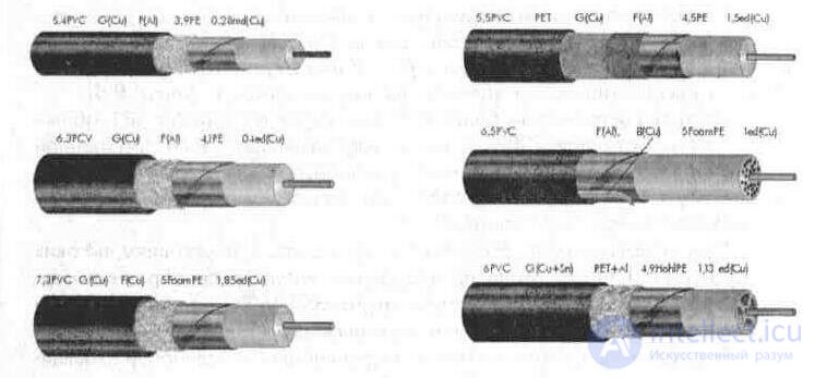
Fig. 6.10. Внешний вид импортных коаксиальных кабелей
- RG (Radio Guide) — «радиоволновод», при маркировке может опускаться (59/U = RG 59/U);
- ЧИСЛОВОЙ КОД — порядковый номер разработки;
- возможен БУКВЕННЫЙ СИМВОЛ, указывающий на различия в конструкции и применении, например: (U) «utility» — сервисный (эффективный).
Так, кабель RG-58 используется при построении локальных компьютерных сетей и в промышленной радиоизмерительной аппаратуре (аналог РК-50), RG-59 — используется в телевизионной и бытовой технике (аналог РК-75).
Встречается также маркировка кабеля (75-4-1, 75-5-В), где:
ПЕРВЫЙ ЭЛЕМЕНТ (цифры) означает волновое сопротивление;
ВТОРОЙ ЭЛЕМЕНТ (цифра) означает округленный диаметр внутреннего диэлектрика;
ТРЕТИЙ ЭЛЕМЕНТ (цифра или буква) означает технологические различия.
Элементы маркировки наносятся на внешнюю защитную оболочку кабеля и разделяются дефисом.
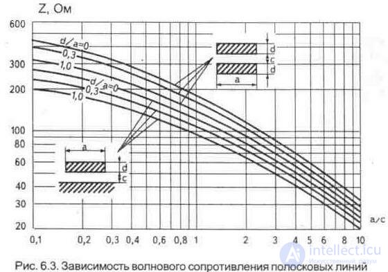
Table 6.16. Reference data
|
Type of coax cable |
Wave resistance W, Ohm |
Spog PF / M |
Deceleration rate, Vк |
Riz / Rnp, MOhm / m (ohm / km) |
Attenuation, dB / m at frequency (GHz) |
|||
|
0.1 |
0.2 |
0.5 |
0.8 (*) |
|||||
|
1.5D-2V |
50 |
|
0.67 |
|
2.85 |
4.1 |
6.483 |
10.0 (1.01 |
|
3D-2V |
50 |
|
0.67 |
|
1.54 |
2.2 |
3.479 |
5.27 (1.0) |
|
5D-2V |
50 |
|
0.67 |
|
0.875 |
0.891 |
2.152 |
3.5 (1.2) |
|
8D-2V |
50 |
|
0.67 |
. |
0.599 |
0.611 |
1.456 |
2.6 (1.2) |
|
10D-2V |
50 |
. |
0.67 |
. |
0.467 |
0.475 |
1.132 |
2.1 (1.2) |
|
20D-2V |
50 |
|
0.67 |
, |
0.292 |
0.296 |
0.755 |
1.5 (1.2) |
|
50-2-1 |
50 ± 4 |
100 |
0.66 |
300 |
0.32 |
0.45 |
0.75 |
0.96 |
|
50-3-1 |
50 + -3 |
100 |
0.66 |
|
0.16 |
0.23 |
0.37 |
048 |
|
50-7-2 |
50 ± 2 |
100 |
0.66 |
. |
0.085 |
0.12 |
0.18 |
026 |
|
50-12-1 |
50 + _ 2 |
100 |
0.66 |
|
Q055 |
0.08 |
0.14 |
0.19 |
|
50 K 155 * |
50 |
100 |
0.79 |
-15 |
0.09 |
0.13 |
0.21 |
0.445 (1.75) |
|
RG 8 Type |
50 + _ 2 |
76.2 |
0.78 |
|
0059 |
0.08 |
0.13 |
0.164 |
|
RG 58A |
50 + _2 |
|
0.78 |
|
0.161 |
0.24 |
0.38 |
0.48 |
|
RG 58C / U |
50 ± 2 |
92.4 |
0.66 |
|
0.16 |
0.24 |
0.39 |
0.493 |
|
RG 58 ALL * |
50 |
82 |
0.78 |
|
0.113 |
0.16 |
0.25 |
0.429 (1.0) |
|
RG 142 b / u |
50 + _2 |
95 |
0, 7 |
|
0.14 |
0.2 |
0.35 |
0.443 |
|
RG 174 A |
50 ± 2 |
101 |
0. 66 |
|
0.29 |
0.45 |
0.7 |
0.885 |
|
RG 174A / U |
50 ± 2 |
92 |
0. 66 |
|
0.29 |
0.45 |
0.7 |
0.885 |
|
RG 178 B / U |
50 + 2 |
95 |
0. 7 |
|
0.43 |
0.62 |
1.02 |
1.29 |
|
RG 188A / U |
50 ± 2 |
95 |
- |
|
0.28 |
0.4 |
0.68 |
0.86 |
|
RG 196 A / U |
50 + _2 |
93 |
0.7 |
|
0.43 |
0.62 |
1 02 |
1.29 |
|
RG213 |
50 + _ 2 |
92 |
0.66 |
|
0.072 |
0.102 |
0.161 |
0204 |
|
RG 213 U |
50 ± 2 |
92 |
0.66 |
|
0.07 |
0.1 |
0.17 |
0.215 |
|
RG 214 U |
50 + _2 |
101 |
0.66 |
|
0.07 |
0.1 |
0.17 |
0.215 |
|
RG215U |
50 + _2 |
101 |
066 |
|
0.07 |
0.1 |
0.17 |
0.215 |
|
RG217U |
50 + _2 |
101 |
0.66 |
|
0.045 |
0.07 |
0.123 |
0.156 |
|
RG 218 U |
50 + _2 |
101 |
0.66 |
|
0029 |
0.045 |
0.081 |
0.102 |
|
RG 219 U |
50 + _2 |
101 |
0.66 |
|
0.029 |
0.045 |
0.081 |
0.102 |
|
RG 220 U |
50 + _2 |
101 |
0.6 |
|
0.023 |
0.038 |
007 |
0.089 |
|
RG 223 U |
50 + _2 |
101 |
0.66 |
|
0.13 |
0.2 |
0 34 |
0.43 |
|
RG 316 U |
50 + _2 |
95 |
. |
|
0.28 |
0.4 |
068 |
0.86 |
|
Belden 9913 |
50 |
. |
0.84 |
|
0043 |
0.061 |
0.096 |
9,121 |
|
Flexi-4XL |
50 |
- |
0.84 |
|
0043 |
0.061 |
0.096 |
0.121 |
|
RLF-7 * |
50 |
75 |
- |
-eight |
0.061 |
0.086 |
0.136 |
0.223 (1.0) |
Table 6.17. Reference data
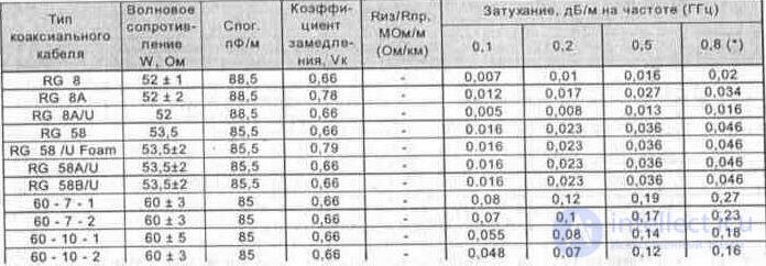
Table 6.18. Reference data
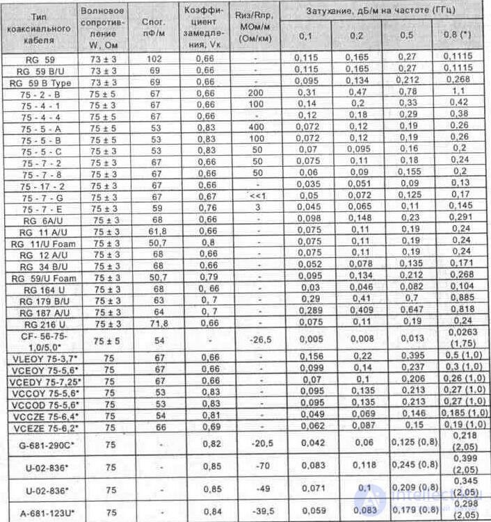
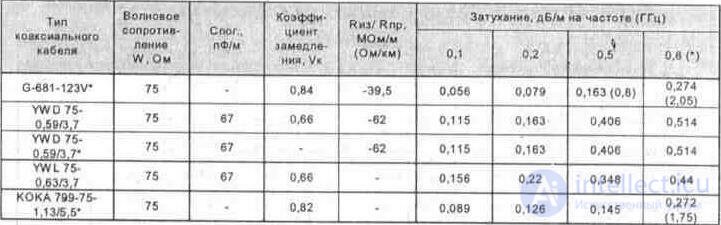
Table 6.19. Reference data
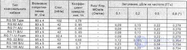
Table 6.20. Reference data
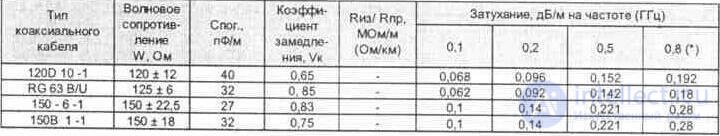
Table 6.21. Reference data
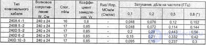
Table 6.22. Reference data

Note: for cables marked with an asterisk, the measurement frequency is also indicated.
There are many ways to determine the parameters of an unknown coaxial cable.
The value of the cable impedance is characterized by the ratio of inductance per unit capacitance. It follows that it depends on the size, shape and relative position of the conductors in its cross section and the dielectric constant of the material of the inner insulation separating the conductors.
DETERMINATION OF THE WAVE RESISTANCE OF A COAXIAL CABLE IN KNOWN GEOMETRIC DIMENSIONS.
First, it is necessary to measure the inner diameter D of the screen (Figure 6.11), removing the protective sheath from the end of the cable and wrapping the braid (outer diameter of the inner insulation). Then measure the diameter d of the central core, removing the pre-isolation. Substituting in the formula 6.4 the value of the dielectric constant of the material of the internal insulation from Appendix 9 and the result of previous measurements, we find the characteristic impedance of the cable.
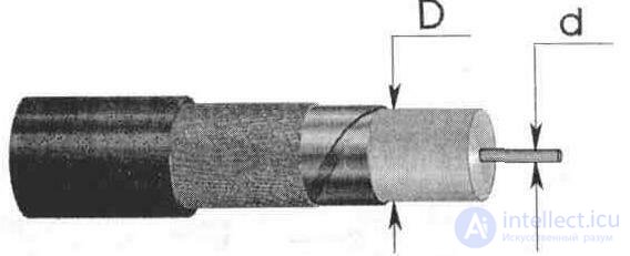
Fig. 6.11. Measurement of the diameters of the internal insulation of an unknown coaxial cable.
In addition, the cable impedance can be determined by the monogram (Figure 6.12).
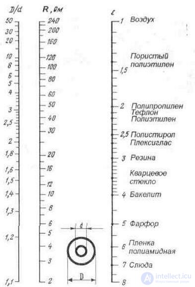
Fig. 6.12. Nomogram to determine the cable impedance
To do this, CONNECT with a straight line DOT d (the ratio of the internal diameter of the screen and the diameter of the inner core) and on the E scale (the dielectric constant of the internal insulation of the cable]. THE CROSSING POINT of the nomogram corresponds to the required wave resistance of the cable being determined.
Unknown characteristic impedance can also be found using the LC measuring bridge, for which:
- connect the device to points А-B (Fig.6.13) of the measured cable of length l;
- measure the capacitance between the central core and the braid {external conductor) of the cable;
- short-circuited points C – D, measure inductance;
- substitute the measured values of inductance (H) and capacitance (F) into the formula 6.11.
Finally, the wave resistance of the cable Z in ohms can be calculated from the results of measurements of the capacitance and the coefficient of shortening the wavelength in the cable according to the formula 6.22:
Z = 3333 • n / Co, (6.22)
where n is the coefficient of shortening the wavelength in the cable;
Co - cable capacity, pf / m.
The cable impedance can also be determined by other methods if, when determining it, the measurement error is no more than ± 2%.
DETERMINATION OF DIELECTRIC PERMEABILITY. In those
In cases where the dielectric constant of the internal insulation of the cable is unknown, it can be calculated using the following method [6.6]:
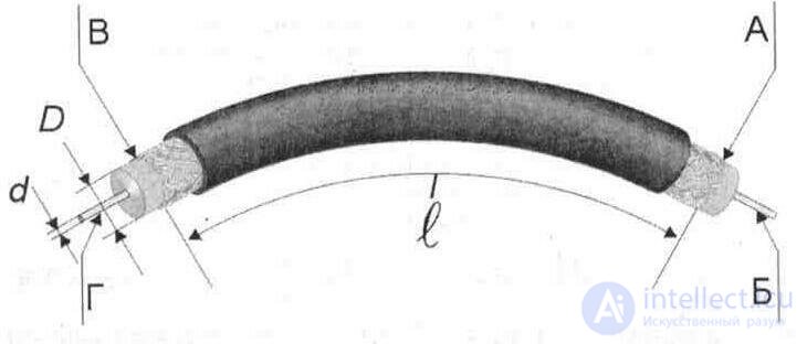
- measure the capacity of the cable segment (Q-meter, or using a capacitance measuring device);
- calculate according to the formula 6.23 the capacity of the previously measured cable length
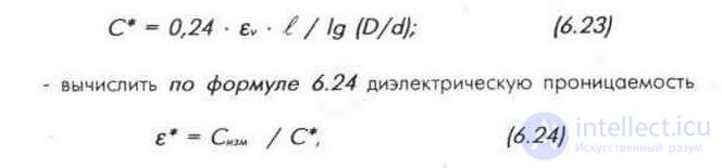
where C * is the calculated capacity of the cable section, pF;
Sim is the measured capacitance of the cable section, pF; il is the length of the segment {not less than 15–20 cm, otherwise the measurement accuracy is reduced), (m);
D is the diameter of the inner insulation. Mm;
d is the diameter of the center conductor, mm.
ev = 1 is the dielectric constant of air;
e * is the calculated dielectric constant.
The device for measuring the capacitance should be connected to the points AB (Fig. 6.13)
DETERMINATION OF THE COEFFICIENT OF CROPPED WAVE LENGTH. If there is no reference data on dielectric constant, then the shortening coefficient can be calculated using the formula
n = с • Z • Со, (6.25)
where n is the coefficient of shortening the wavelength;
Z is the wave resistance of the cable, Ohm;
Co is the linear capacitance of the cable, F / m;
c = 3 * 10 ^ 8 m / s is the wave propagation velocity.
The formula allows determining the shortening factor not only in coaxial cables, but also in other lines (without losses or with small losses), if their characteristic impedances and linear capacitances are known.
UNIFORMITY OF WAVE RESISTANCE over cable length is expressed in the values of local reflection coefficients and is measured by the pulse method using time reflectometers. Measurements are also carried out sequentially from two ends of the cable.
NON-DIMENSIONAL WAVE RESISTANCE is a measure of the change in the frequency band of the normalized input resistance of a cable loaded on a matched load, and is expressed by the value of the SWR or the twenty- fold decimal logarithm of the reciprocal of the modulus of the input reflection coefficient p in (dB)
SWR = 20 Ig1 / p in. (6.26)
It is measured from two ends of the cable using panoramic methods with the use of frequency reflectometers or meters of 5-parameters of two-port networks (P4-11).
DIFFUSION RATIO (c) is measured at the frequency specified in the standard or specification. The value in is measured in dB / m, except for cables with helical conductors, for which in is expressed in dB / μs.
It is recommended to use panoramic attenuation coefficient measurement methods. At frequencies below 0.2 GHz, measurement methods on the resonant frequency f *, closest to the one at which the damping is normalized, are allowed. To determine the attenuation coefficient at other frequencies, you can use the formula

where * is the known values of the attenuation coefficients at the frequency f *, dB / m;
f is the frequency for which the attenuation coefficient p is recalculated.
The formula is valid for feeders with an air dielectric, and for feeders with other dielectrics - only up to the frequency f = 300 MHz.
ELECTRIC CAPACITY OF SYMMETRIC CABLE and CAPACITIVE ASSYMMETRY is measured at frequencies of 800 Hz or more. Measurements are made using an AC bridge or another device that can be used to measure the capacitance at the specified frequencies with an accuracy of ± 1%. Electrical capacitance (C) in picofarads per meter and capacitive asymmetry (e) in percent of symmetric cables with a common screen for both insulated conductors are calculated by the formulas:
C = [2 (C1 + C2) - C12] / 4 * l (6.28) e = 400 (C1 - C2) / [2 (C1 + C2) - C12], (6.29)
where C1 is the electrical capacitance between the first and second
residential, connected to the screen, pF;
C2 - electric capacity between the second and first
residential, connected to the screen, pF;
C12 - electrical capacitance between connected together
first and second cores and screen, pF;
/ - sample length, m
The sample length must be at least 1 m and not more than a number, the value of which in meters is equal to
/ = 20 / f • n, (6.30)
where: f - measurement frequency, MHz;
n is the coefficient of shortening the wavelength in the cable.
When installing coaxial cables, it is necessary to observe the minimum bending radii (specified in the standard or specifications for cables of different brands). So, for the cable RC-75-4-11, the minimum bending radius for t> + 5 ° C is 40 mm, and for t <+ 5 ° C it is 70 mm. Bending the cable under a smaller radius is not recommended. It should also be borne in mind that under the action of its own weight the cable is drawn out. This should be considered when laying the cable (vertical) and between buildings. It should be fixed to the wall (mast) or auxiliary cable every 1-2 meters.
When storing cables with air and semi-air insulation, their ends should be protected from moisture penetration into the cable, and during operation it is necessary to use sealed connectors.
It is possible to splice two pieces of coaxial cable 1 in the manner shown in fig. 6.14, for which the parts of the central conductors of cables exempt from the insulation must be shortened as much as possible. Places of soldering conductors should not have significant thickenings, so the central (internal) conductors partially cut the file (one side of the conductor will be flat). After tin-lead solder, the sawed ends of the conductors are laid on each other and sealed. In order not to change the characteristic impedance, it is necessary to restore the internal insulation 3 on the site of the spliced part of the cable (prefabricated from the internal polyethylene insulation removed from the cable). Detail 2 is cut out of tin or
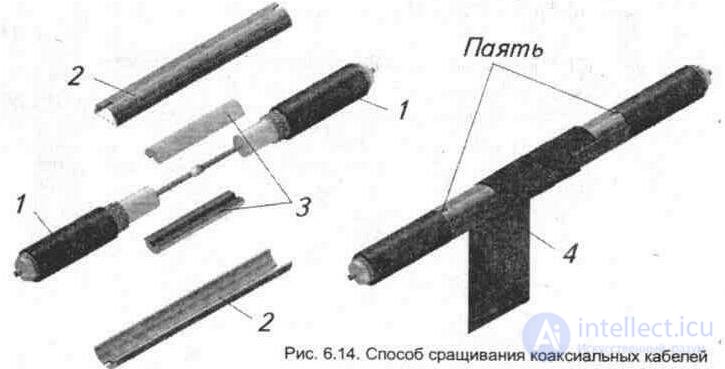
copper foil with a thickness of about 0.1 ... 0.2 mm and set on top of the connected section with restored insulation 3. Braid of cables should be soldered at the cut-out points of part 2. To give strength to connection part 2 along the entire length, it is advisable to wrap tightly with tape 4.
When soldering the central core, it should not be allowed to overheat, since this causes a displacement and impedance homogeneity is disturbed.
When installing cables and cutting braids, the latter cannot be cut: the braid must be tied up, twisted into one or two pigtails and tinted. When splitting the cable, it is necessary to ensure that the central core is not accidentally trimmed and so as not to short-circuit the wire braid on it.
The effectiveness of shielding the coaxial line, which is defined as the ratio of the energy transmitted inside the coaxial line to the energy that seeps into external space, should be taken into account. The effectiveness of shielding a coaxial cable can be judged by its design: the higher the density of the external conductor (screen), the greater the value of this parameter. Cables with an additional screen sheath (Fig. 15) of foil (copper, aluminum) have the highest value of screening efficiency.
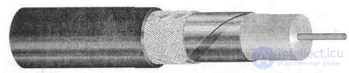
Fig. 6.15. Coaxial cable with additional shield
The effectiveness of shielding new ones, i.e. not used coaxial lines, is 60-100 dB.
The linear attenuation in a coaxial cable of the RK type can be judged by its design: the larger the diameter of the internal insulation of cables (in the designation of the cable brand, it is indicated in millimeters after the number 75), the smaller its specific attenuation.
Coaxial cable, or coax (pronounced /ˈkoʊ.æks/) is a type of electrical cable consisting of an inner conductor surrounded by a concentric conducting shield, with the two separated by a dielectric (insulating material); many coaxial cables also have a protective outer sheath or jacket. The term "coaxial" refers to the inner conductor and the outer shield sharing a geometric axis.
Coaxial cable is a type of transmission line, used to carry high-frequency electrical signals with low losses. It is used in such applications as telephone trunklines, broadband internet networking cables, high-speed computer data busses, cable television signals, and connecting radio transmitters and receivers to their antennas. It differs from other shielded cables because the dimensions of the cable and connectors are controlled to give a precise, constant conductor spacing, which is needed for it to function efficiently as a transmission line.
Coaxial cable was used in the first (1858) and following transatlantic cable installations, but its theory wasn't described until 1880 by English physicist, engineer, and mathematician Oliver Heaviside, who patented the design in that year (British patent No. 1,407).[1]
продолжение следует...
Часть 1 6. Feeder lines (antenna power devices) Coaxial cable, or coax

Comments
To leave a comment
Television and antennas. Theory. Broadcast and cable. Digital and analog
Terms: Television and antennas. Theory. Broadcast and cable. Digital and analog