Lecture
1.1. Frequency channels of television and VHF FM broadcasting.
The descriptions of various types of antennas and other antenna-feeder devices, as well as the related consideration of theoretical issues, are carried out using the classification of oscillations by wavelength (Table 1.1) in accordance with the Radio Regulations adopted by the International Radio Advisory Committee (CCIR).
Table 1.1. Radio spectrum frequency bands
nom | Frequency range (excluding the lower limit, including the upper limit) | Letter designation lanes | Metric name in accordance with the Radio Regulations | The name of the radio waves used in the literature |
four | 3 - 30 kHz | VLF (VLF) | Miriametrovye | Extra Long (ADL) |
five | 30 - 300 kHz | LF (LF) | Kilometers | Long (DV) |
6 | 0.3 - 3 MHz | SC (MF) | Hectometric | Medium (SV) |
7 | 3 - 30 MHz | HF (HF) | Decameter | Short (KB) |
eight | 30 - 300 MHz | VHF (VHF) | Meters | Ultrashort (VHF) |
9 | 0.3 - 3 GHz | UHF (UHF) | Decimeter | Ultrashort (VHF) |
ten | 3-30GHz | Microwave (SHF) | Centimeter | Ultrashort (VHF) |
eleven | 30 - 300 GHz | EHF (EHF) | Millimeter | Ultrashort (VHF) |
12 | 300-3000 GHz | Ghv | Decimillimeter | Ultrashort (VHF) |
For VHF FM broadcasting and television, the eighth meter band and the ninth band of decimeter waves are used. The whole range of frequencies allocated for TV broadcasting and VHF FM broadcasting is divided into bands designated by Roman numerals I - V (Table 1. 2). For terrestrial TV broadcasting, the development of the tenth and eleventh bands is provided - VI range (12 GHz, 40, 5 ... 42, 5 GHz and 84 ... 86 GHz). Bandwidth of one TV channel
(according to the standard MORT) 8 MHz, the separation between the carrier frequencies of the image and sound signals is 6. 5 MHz.
Table 1. 2. Radio wave bands and frequency bands
Broadcast Frequency Range | Channel TV number | lср channel, m | fср channel, MHz | Frequency band | Carrier frequency | ||
channel, MHz | Images, MHz | sound, MHz | |||||
METRO | WAVES | VHF | (Vhf) | ||||
I | one | 5.72 | 52.5 | 48.5-56.5 | 49.75 | 56.25 | |
| I | 2 | 4.84 | 62 | 58-66 | 59.25 | 65.75 | |
VHF FM RADIO | |||||||
66-73 | Standard MORT (Eastern Europe) | ||||||
87, 5-108 | ICRC Standard (Western Europe) | ||||||
METRO | VHF WAVES (VHF) | ||||||
II | 3 | 3.75 | 80 | 76-84 | 77.25 | 83.75 | |
II | four | 3.41 | 88 | 84-92 | 85.25 | 91.75 | |
II | five | 3.13 | 96 | 92-100 | 93.25 | 99.75 | |
1-CABLE | STRIP | (SK-1 ... 8 | or S-1 ... 8) | ||||
S-1 | 114 | 110-118 | 111.25 | 117.75 | |||
S-2 | 122 | 118-126 | 119.25 | 125.75 | |||
S-3 | 130 | 126-134 | 127.25 | 133.75 | |||
S-4 | 138 | 134-142 | 135.25 | 141.75 | |||
S-5 | 146 | 142-150 | 143.25 | 149.75 | |||
S-6 | 154 | 150-158 | 151.25 | 157.75 | |||
S-7 | 162 | 158-166 | 159.25 | 165.75 | |||
S-8 | 170 | 166-174 | 167.25 | 173.75 | |||
METRO | WAVES | VHF | (Vhf) | ||||
III | 6 | 1.69 | 178 | 174-182 | 175.25 | 181.75 | |
III | 7 | 1.61 | 186 | 182-190 | 183.25 | 189.75 | |
III | eight | 1.55 | 194 | 190-198 | 191.25 | 197.75 | |
III | 9 | 1.49 | 202 | 198-206 | 199.25 | 205.75 | |
III | ten | 1.43 | 210 | 206-214 | 207.25 | 213.75 | |
III | eleven | 1.38 | 218 | 214-222 | 215.25 | 221.75 | |
III | 12 | 1.33 | 226 | 222 - 230 | 223.25 | 229.75 | |
2-CABLE | (CK-11. 18 | or S-11 ... 19) | |||||
S11 | 230 - 238 | 231.25 | 237.75 | ||||
S12 | 238 - 246 | 239.25 | 245.75 | ||||
S13 | 246 - 254 | 247.25 | 253.75 | ||||
S14 | 254 - 262 | 255.25 | 261.75 | ||||
S15 | 262 - 270 | 263.25 | 269.75 | ||||
Continued table. 1.2.
Broadcast Frequency Range | Channel TV number | lср channel. m | fср channel, MHz | Channel bandwidth, MHz | Carrier frequency | |
images, MHz | sound. MHz | |||||
2-CABLE | STRIP | (SK-11 .. 18 | or S-11 ... 19) | |||
S16 | 270-278 | 271.25 | 277.75 | |||
S17 | 278-286 | 279.25 | 285.75 | |||
S18 | 286-294 | 287.25 | 293.75 | |||
S19 | 294-302 | 295.25 | 301.75 | |||
3-CABLE | Strip | range | Super | bond | ||
S20 | 302-310 | 303.25 | 309.75 | |||
S21 | 310-318 | 311.25 | 317.75 | |||
S22 | 318-326 | 319.25 | 325.75 | |||
S23 | 326 -334 | 327.25 | 333.75 | |||
S24 | 334 - 342 | 335.25 | 341.75 | |||
S25 | 342-350 | 343.25 | 349.75 | |||
S26 | 350 -358 | 351.25 | 357.75 | |||
S27 | 358-366 | 359.25 | 365.75 | |||
S28 | 366-374 | 367.25 | 373.75 | |||
S29 | 374 - 382 | 375.25 | 381.75 | |||
S30 | 382 - 390 | 383.25 | 389.75 | |||
S31 | 390-398 | 391.25 | 397.75 | |||
S32 | 398-406 | 399.25 | 405.75 | |||
S33 | 406-414 | 407.25 | 413.75 | |||
S34 | 414-422 | 415.25 | 421.75 | |||
S35 | 422-430 | 423.25 | 429.75 | |||
S36 | 430-438 | 431.25 | 437.75 | |||
S37 | 438 -446 | 439.25 | 445.75 | |||
S38 | 446-454 | 447.25 | 453.75 | |||
S39 | 454-462 | 455.25 | 461.75 | |||
S40 | 462-470 | 463.25 | 469.75 | |||
Decimeter | waves | VHF | (U H F) | |||
IV | 21 | 0.632 | 474 | 470-478 | 471.25 | 477.75 |
IV | 22 | 0.622 | 482 | 478-486 | 479.25 | 485.75 |
IV | 23 | 0.612 | 490 | 486-494 | 487.25 | 493.75 |
IV | 24 | 0.602 | 498 | 494 - 502 | 495.25 | 501.75 |
IV | 25 | 0.592 | 506 | 502 - 510 | 503.25 | 509.75 |
IV | 26 | 0.583 | 514 | 510-518 | 511.25 | 517.75 |
IV | 27 | 0.574 | 522 | 518-526 | 519.25 | 525.75 |
IV | 28 | 0.566 | 530 | 526 - 534 | 527.25 | 533.75 |
IV | 29 | 0.557 | 538 | 534 - 542 | 535.25 | 541.75 |
IV | thirty | 0.549 | 546 | 542-550 | 543.25 | 549.75 |
IV | 31 | 0.541 | 554 | 550 -558 | 551.25 | 557.75 |
IV | 32 | 0.533 | 562 | 558- 566 | 559.25 | 565.75 |
IV | 33 | 0.526 | 570 | 566 -574 | 567.25 | 573.75 |
IV | 34 | 0.519 | 578 | 574 -582 | 575.25 | 581.75 |
Continued table. 1.2.
Broadcast Frequency Range | Channel TV number | lср kana-la.m | fср channel. MHz | Strip | Carrier frequency | |
channel, MHz | images, MHz | sound, MHz | ||||
DZIMETROVYE WAVES | OB H (UHF) | |||||
V | 35 | 0.512 | 586 | 582-590 | 583.25 | 589.75 |
V | 36 | 0,505 | 594 | 590 -598 | 591.25 | 597.75 |
V | 37 | 0.498 | 602 | 598 - 606 | 599.25 | 605.75 |
V | 38 | 0,491 | 610 | 606-614 | 607.25 | 613.75 |
V | 39 | 0.485 | 618 | 614-622 | 615.25 | 621.75 |
V | 40 | 0.479 | 626 | 622-630 | 623.25 | 629.75 |
V | 41 | 0.473 | 634 | 630-638 | 631.25 | 637.75 |
V | 42 | 0.467 | 642 | 638-646 | 639.25 | 645.75 |
V | 43 | 0.461 | 650 | 646- 654 | 647.25 | 653.75 |
V | 44 | 0.456 | 658 | 654 - 662 | 655.25 | 661.75 |
V | 45 | 0.450 | 667 | 662-670 | 663.25 | 669.75 |
V | 46 | 0.445 | 674 | 670-678 | 671.25 | 677.75 |
V | 47 | 0.440 | 682 | 678-686 | 679.25 | 685.75 |
V | 48 | 0.435 | 690 | 686-694 | 687.25 | 693.75 |
V | 49 | 0.430 | 698 | 694 - 702 | 695.25 | 701.75 |
V | 50 | 0.425 | 706 | 702-710 | 703.25 | 709.75 |
V | 51 | 0.420 | 714 | 710-718 | 711.25 | 717.75 |
V | 52 | 0.415 | 722 | 718 - 726 | 719.25 | 725.75 |
V | 53 | 0.411 | 730 | 726-734 | 727.25 | 733.75 |
V | 54 | 0.406 | 738 | 734- 742 | 735.25 | 741.75 |
V | 55 | 0.402 | 746 | 742-750 | 743.25 | 749.75 |
V | 56 | 0.398 | 754 | 750-758 | 751.25 | 757.75 |
V | 57 | 0.393 | 762 | 758-766 | 759.25 | 765.75 |
V | 58 | 0.389 | 770 | 766-774 | 767.25 | 773.75 |
V | 59 | 0.385 | 778 | 774-782 | 775.25 | 781.75 |
V | 60 | 0.381 | 786 | 782-790 | 783.25 | 789.75 |
V | 61 | 0.378 | 794 | 790-798 | 791.25 | 797.75 |
V | 62 | 0.374 | 802 | 798-806 | 799.25 | 806.75 |
V | 63 | 0.370 | 810 | 806-814 | 807.25 | 813.75 |
V | 64 | 0.367 | 818 | 814-822 | 815.25 | 821.75 |
V | 65 | 0.363 | 826 | 822-830 | 823.25 | 829.75 |
V | 66 | 0,359 | 834 | 830-838 | 831.25 | 837.75 |
V | 67 | 0.356 | 842 | 838-846 | 839.25 | 845.75 |
V | 68 | 0.353 | 850 | 846-854 | 847.25 | 853.75 |
V | 69 | 0.349 | 858 | 854-862 | 855.25 | 861.75 |
V | 70 | 0.346 | 866 | 862 - 870 | 863.25 | 869.75 |
V | 71 | 0.343 | 874 | 870-878 | 871.25 | 877.75 |
V | 72 | 0.340 | 882 | 878-886 | 879.25 | 885.75 |
V | 73 | 0.337 | 890 | 886 - 894 | 887.25 | 893.75 |
V | 74 | 0.334 | 898 | 894 - 902 | 895.25 | 901.75 |
V | 75 | 0.331 | 906 | 902-910 | 903.25 | 909.75 |
Continued table. 1.2.
Broadcast Frequency Range | Channel TV number | lср channel, m | channel channel, MHz | Channel bandwidth, MHz | Carrier frequency | |
images, MHz | sound, MHz | |||||
Decimeter | waves | OB H (UHF) | ||||
V | 76 | 0.328 | 914 | 910-918 | 911.25 | 917.75 |
V | 77 | 0.325 | 922 | 918-926 | 919.25 | 925.75 |
V | 78 | 0.322 | 930 | 926 - 934 | 927.25 | 933.75 |
V | 79 | 0.379 | 938 | 934-942 | 935.25 | 941.75 |
V | 80 | 0.317 | 946 | 942 - 950 | 943.25 | 949.75 |
1. 2. Transmission of television signals
The transmission of television signals is conducted at strictly fixed frequencies allocated on the basis of the grid of frequency channels for a given installation site of the transmitting station. The grid of frequencies for a given installation site of television transmission centers is constructed in such a way as to cover the maximum broadcasting territory and exclude mutual interference of reception from telecentres operating on adjacent channels. Therefore, the distance between the transmitting television stations operating on the same TV channels, to avoid mutual interference, is approximately 300-400 km.
In addition, each country plans transmission networks on the basis of its economic capabilities, with the result that separate frequency incompatibilities appear.
When planning a television network using data [1. 1], determining the service area of television broadcasting (at the corresponding gain values of the receiving television antennas). For satisfactory quality of the received image it is necessary to use antennas, the gain of which is indicated in Table. 1. 3. Here, E is the minimum value of the intensity of the radiation field of a radio signal of an image at a height of 10 m from the surface of the Earth, taken in decibels relative to 1 µV / m.
In television broadcasting, two types of wave polarization are used - horizontal and vertical. The use of vertical wave polarization in television broadcasting allows reducing the protection ratios for stations and repeaters operating on co-located and adjacent channels, which makes it possible to additionally use TV channels or reduce mutual interference from closely located telecentres. The use of different polarization allows reducing the allowable distances between them on the I, II range of broadcasting by 20%, and on the III range - up to 25% ... 30%.
Table 1. 3. Minimum values of the intensity of the radiation field of a radio signal
frequency range | transmission frequency, MHz | E, mV / m | E, DB | antenna gain Db |
| | 48, 5-66 | 316 | 50 | four |
II | 76-100 | 501 | 54 | 4, 5 |
III | 174-230 | 708 | 57 | eight |
IV | 470-582 | 3162 | 70 | ten |
V | 582-790 (958) | 5000 | 74 | 15-18 |
1. 2. 1. Transmitting stations and repeaters
Television stations are divided into program and transmission. Software TV stations are television centers whose equipment ensures the reception of television broadcast signals with their subsequent transmission over a television transmission network. Transmitting television stations provide programs created in television centers.
According to the power of the image signal at the output of the television transmitter, the stations are conventionally subdivided into powerful (or high power) - more than 1 kW and low power - less than 1 kW. The transmission distance of programs by television centers slightly exceeds the line-of-sight distance between transmitting and receiving antennas, therefore transmitting stations are placed at a distance of 70 .. L 20 km.
In order to cover as wide a territory as possible with television broadcasting, television transmitting antennas are installed on high supports using natural terrain heights. Antenna support is a high-rise structure, which by design is divided into towers (H = 150 ... 550 m) and masts (H = 200 ... 350 m).
Panel, turnstile and antennas with radial and corner vibrators are used as transmitters.
The basic requirements that transmitting antennas must meet are the indiscriminate radiation of radio signals and the creation of the most uniform intensity. electromagnetic field in the service area.
The most important parameters of transmitting television antennas include:
- gain or directional gain;
- the shape of the radiation pattern (directivity) in the horizontal and vertical planes;
- polarization of radiated waves, etc.
To create the maximum field strength in the zone, the radiation power is increased, but at low elevation heights of the antenna, the field strength in the near zone may exceed the permissible sanitary norms.
The gain of transmitting antennas (relative to an isotropic radiator) in the 1-11 ranges is 6 ... 10, in the III range - up to 25, and for UHF ranges of the IV-V - up to 50.
For antennas with a high gain in the radiation pattern in the vertical plane, the number of side lobes increases, which is why at close distances from the transmitting station there appear areas with insufficient field strength for normal reception of television programs.
Of importance is the constancy of the input impedance of the antenna within the transmission band, determined by the TRAVELING WAVE RATIO (IPM) in the feed feeder. Transmitting antennas should provide an IPA of about 0, 9 in the transmission band.
To extend the service area and increase the level of the television signal in areas where there is an uncertain reception from the main television stations, a television repeater is used. Being a type of television stations, a television repeater is designed to receive and transmit programs of remote television centers with the possibility of changing the direction of radiation. Repeaters are divided into active and passive.
Passive repeaters allow you to change the direction of propagation of the television signal. However, they significantly weaken the field strength, so they can be used only with a sufficient signal level at the installation site (Fig. & 1. 1). Passive repeaters can be made in the form of reflective planes (metal mirror) or phased arrays. In the first case, these are flat single-line wire grids with a sufficiently high reflection coefficient, with cells of 0.1l in size (l is the average wavelength of re-emitted waves), and a turning device is provided for changing its position. Such repeaters can operate in a wide frequency range and re-emit the received energy of several channels simultaneously. In the second case, these are antennas, for example, of the "wave channel" type, forming two grids connected to each other. The signal energy received by one grid is emitted by another identical grid in the desired direction. The working frequency range is determined by the antennas used in it. To obtain good reception quality from a passive repeater, a direct signal at the reception site must be sufficiently weak and not create noticeable repetitions on the image.
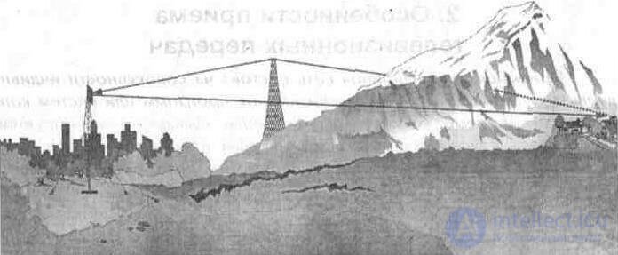
Fig. 1. 1. Use of passive repeater
There is a large number of active repeaters in operation, of various purposes and operating parameters, intended for use in all television bands and having output power from 0, 1 W to 1 kW. Their main varieties are repeater-amplifier, repeater-transducer and repeater-transmitter. The television signal goes to the repeater as well as to the powerful transmitting stations - via radio relay lines, high-frequency cables, satellite communication systems, or directly over the air. The type of transmitting antennas is chosen taking into account the location of the service area and the installation site of the repeater. If the transponder is installed in the center of a populated area, then a transmitting antenna with a circular radiation pattern in the horizontal plane is applied, uniformly radiating power in all directions. Transmitting antennas with directional radiation are usually installed on repeaters located on the outskirts or outside settlements. The range of repeaters is limited by their output power, Pout (see table. 1. 4).
Table 1. 4. The range of the repeaters.
Pout W | Range, km | |
VHF | UHF | |
one | 5 ... 6 | 2 ... 3 |
ten | 10 ... 12 | 4 ... 5 |
100 | 20 ... 30 | 8 ... 10 |

Comments
To leave a comment
Television and antennas. Theory. Broadcast and cable. Digital and analog
Terms: Television and antennas. Theory. Broadcast and cable. Digital and analog