Lecture
The conditions of propagation of radio waves in a room are significantly different from their propagation in free space. The interference pattern of the electromagnetic field inside the premises (due to multiple reflections from objects) is more pronounced. This is manifested in a decrease in the field strength and a change in the polarization of the waves. The acceptable antenna layout for one TV channel may not match its location for receiving another channel. The quality of reception on indoor and indoor antennas can vary even when people walk around the room.
The magnitude of the received signal is influenced by the shielding properties of the materials of the building walls (in houses built of reinforced concrete structures, the attenuation of signals is 3-5 times more than in wooden ones) Therefore, it is better to have indoor antennas close to the windows. In densely built-up areas, the field strength on the lower floors is 10-20 times (on the upper 5-8 times) less than on the roof of the building.
In apartments, where the windows face the side opposite to the center of the body, the field strength is so small that it does not allow for a satisfactory reception of TV programs. Installation of lattices and shading metal curtains on the windows and balconies leads to a further reduction of the television signal, and sometimes to the impossibility of viewing previously received programs for indoor antennas.
High-quality reception of TV programs for indoor antennas is possible under the condition of direct visibility and the location of the apartment on the upper floors of the building (with multi-storey buildings).
If it is not possible to install an outdoor antenna, you need to check the operation of your TV on the neighbor's indoor antenna, and then make a decision about purchasing it.
A variety of indoor antennas are built-in antennas used in portable televisions. By design, it is a meter (telescopic) one-pin or two-pin antenna. For reception in the range of decimeter waves, a loop antenna is used. Single-antenna is connected directly to the input of the TV, two-pin and frame - through a balun transformer. In the working position, the antenna is extended and can be installed vertically or tilted. Depending on the received television channel, the length of the pins of the telescopic antenna is selected. Receiving ns built-in antennas is possible with sufficient television signal power.
Currently, there are commercially available indoor antennas of various kinds, when buying, you need to choose from them those that are suitable for receiving the necessary television channels in the area. Receiving television channels indicate in the passport to the antenna.
According to GOST [3. 1] The symbol for indoor antennas begins with the letters:
AT - television antenna;
the third letter in the designation indicates the ability of the antenna for restructuring P - tunable, N - non - tunable);
the first digit is the antenna type;
the second is the development number (modification);
FOR EXAMPLE: ATP - 6.1 - a television antenna, tunable, 6th type, first modification;
ATN - 6.2 - television antenna, non-tunable, 6th type, second modification.
To receive meter waves, indoor antennas are made on the principle of half-wave or shortened linear vibrators. The most common telescopic room antenna meter range with swivel device (Fig. & 3. 3).
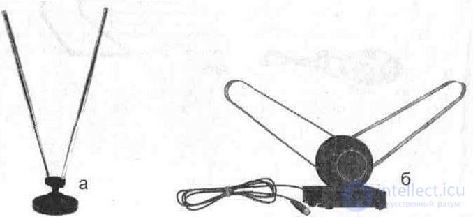
Fig. 3. 3. Telescopic indoor antenna:
a) pin, b) tape
The hinge device allows you to find the optimal position, and the telescopic design of the vibrators - to tune to the received television channel. To match the vibrators of indoor antennas with a 75-ohm cable, a balancing transformer is used.
In some indoor antennas, shortening inductances are used to reduce the geometric length of the vibrators and facilitate their adjustment.
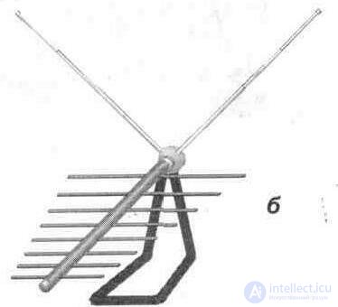
In the decimeter wavelength range, the geometrical dimensions of the antennas are significantly less than in the meter range, as a result of which it became possible to manufacture and use small-sized directional efficient antennas - “wave channel”, log-periodic and others (Fig. 3. 4).
In cases where reception on a room antenna is unsatisfactory, it is necessary to install an outdoor TV antenna, and if this is not possible (due to the building structure, lack of a balcony, etc.), you should install a room television antenna with an amplifier. The amplifier is structurally embedded into the base of the antenna. It is advisable to apply when receiving weak signals and the absence of interference (the operation of industrial installations, electric vehicles, etc.).
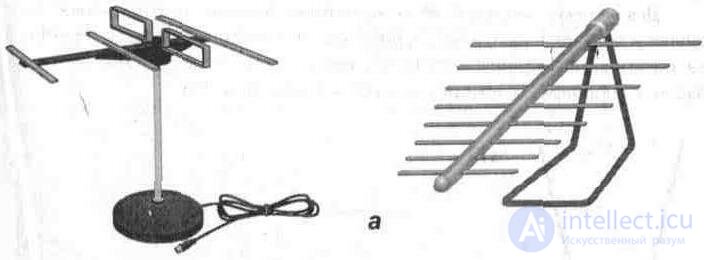
Fig. 3. 4. Appearance of indoor antennas:
a) for receiving UHF channels
b) to receive MB and UHF channels
3.2.1. Room antenna ATN - 7.3 "ORBIT-II-I" with an amplifier
To enhance the amplifying properties of indoor antennas used antenna amplifier. These antennas include the ATN-7.3 “ORBITA-II-I” television room broadband antenna with an amplifier (Fig. 3.5). It is convenient to connect to televisions of domestic production, with separate outputs MB and UHF bands.
Signals of a meter wave band receive a wideband flat vibrator, and a decimeter one - a four-element wave channel, structurally located on a stand above a broadband flat vibrator. The amplifier, located inside the antenna case, is used to improve the reception of television channels in the decimeter wavelength range. The amplifier circuit diagram is shown in Fig. 3.6.
Technical specifications:
Antenna gain, with respect to a half-wave vibrator, dB, not less than in the 48, 5 ... 100 MHz MB range ......................... .................................................. ...... -2
in the MB range of 174 ... 230 MHz ......................................... ........................................ ABOUT
UHF range 470 ... 620 MHz .......................................... ........................................ 15
Coefficient of traveling wave (KBV), (measured at the end of the descent cable), not less, in the frequency band:
48, 5 ... 100 MHz .......................................... .................................................. ................. 0, 2
174 ... 230 MHz ............................................ .................................................. ................ 0, 4
470 ... 620 MHz ............................................ .................................................. ................ 0, 4
Protective action coefficient (KZD), dB, not more than, in the frequency band
48, 5 ... 100 MHz .......................................... .................................................. ................. ABOUT
174 ... 230 MHz ............................................ .................................................. ................ ABOUT
470 ... 620 MHz ............................................ .................................................. ............... -eight
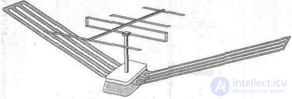
Fig. 3. 5. Antenna television room broadband ATH-7. 3 "ORBIT-II-I"
The signal received by the antenna decimeter range, through the capacitance C1 is supplied to the base of the transistor VT1, made according to the scheme with a common emitter. The amplified signal from the collector VT1 through C4, W2 is fed to the input of the second amplifying stage on the transistor VT2. Formation of the frequency response is carried out by elements C1W1, C4W2 at the input and output VT1. The current feedback in the amplifier stages is determined by the elements C5R4C6, C8R8C9. The amplified signal through the capacitance C10 is fed to the output connector SX2 and then goes through the feeder to the power supply. Through the capacitance C1 is the separation of the television signal and the supply voltage (+ 12 V). Regulate the voltage supply adjusted resistor R1. Strip lines W1 ... W4 are made by the method of printed wiring.
3. 2. 2. Indoor antenna with adjustable gain The disadvantages of indoor antennas with an amplifier include the possibility of sharply pronounced repeated images (with inaccurate orientation), as well as the imposition of another more powerful program on the main image signal. In close proximity to the telecentre, a large gain antenna with an amplifier leads to a breakdown of synchronization and the inability to view powerful television channels.
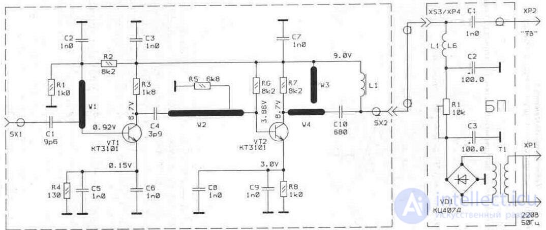
Fig.3.6. Schematic diagram of the amplifier room antenna ATN 7-3 "ORBIT-11-1"
cash. Therefore, when receiving various TV channels, you have to choose the position of the antenna in the room each time. These disadvantages can be avoided by using an indoor antenna with adjustable gain.
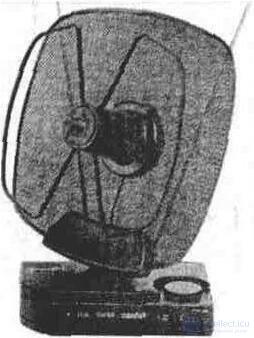
Fig. 3.7. General view of the antenna with adjustable gain
Reception of television channels of a meter range of waves happens on one-pin or two-pin (depending on execution) telescopic antenna, and decimeter - on a zigzag antenna with a parabolic reflector. The antenna amplifier and power supply unit are structurally located inside the stand case (Fig. 3.7). Adjustable amplifier operates as follows (Fig. 3.8). Through the device of the addition of signals (low pass filter L1C3L2 and high pass filter C1C2L3C4) the television signal is fed to the transistor VT1. Using the regulator R18, located on the body of the antenna, changes the supply voltage of the transistor VT1, which leads to a change in its gain.
The formation of the frequency response of the amplifier is determined by the elements C7R4L4C10, C13R10L5 and the current feedback elements R3C8R6, R9C12R12. The gain control is controlled by two LEDs - a green and a red glow: when the green lights up, the minimum voltage is applied, which corresponds to the minimum gain, and when the red LED lights up, the maximum voltage (gain maximum). The disadvantage of this antenna is the small size of the telescopic antenna (single-pin version) and, as a result, poor reception on 1-5 meter channels. The best parameters for receiving TV channels of the meter range are antennas with a two-pin telescopic design.
It should be noted that it is more convenient to use the antenna designs discussed above with televisions that have a combined input for the meter and decimeter bands.
ACTIVE ANTENNAS are commonly referred to as devices that combine the antenna itself and the active elements of signal conversion gain. It is impossible to separate the active antenna but the passive and active parts, since it is performed as a single unit.
3. 2. 3. Active antenna "DELTA"
The types of active antennas is the antenna DELTA (Fig. 3. 9). The antenna comes with a stand and a mast mount used to mount the antenna outdoors.
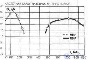
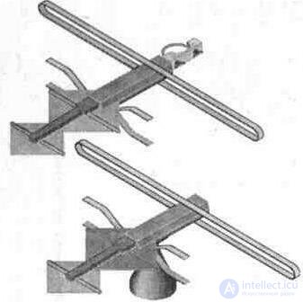
Fig. 3. 9. The appearance of the antenna "DELTA"
Technical parameters of the antenna "DELTA":
Reception Channels ................................................ .. 1-5 ................. 6-12 ................ 21 -68
Amplification, dB ............................................... ...... 8 ...................... 25 .................... 28
Reception angle ................................................ ....... 2x90 ° ............... 2x90 ° ................ 60 °
KZD, dB ................................................... .............. 0 ...................... 0 ............ ........... sixteen
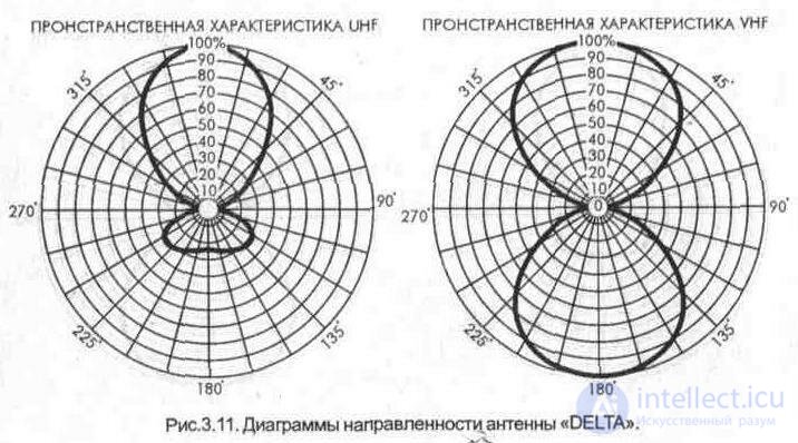
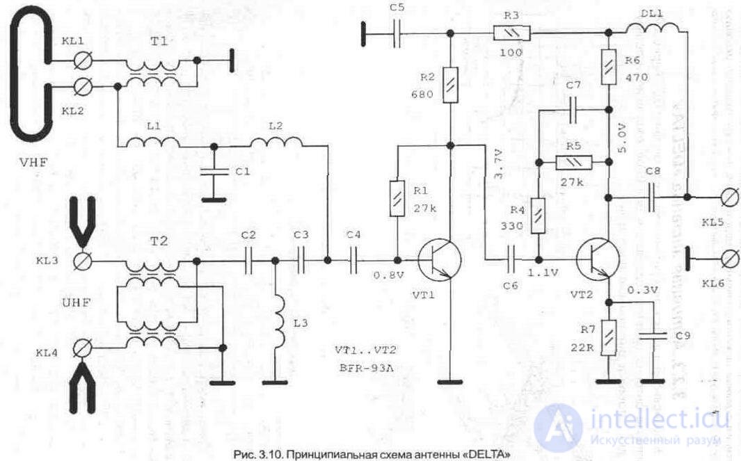
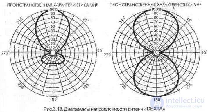
Reception meter range of waves is carried out on a loop vibrator, and a decimeter - on the wave X-shaped vibrator (Fig. 3. 10). The matching with the addition filters is carried out by transformers T1 and T2. Through the device of addition of signals (lowpass filter L1C1L2 and highpass filter C2L3C3) the television signal is fed to a two-stage amplifier.
Correction of the frequency response in the second stage is carried out by the elements R4R5C7 and C9R7. Amplifier power (+ 12V) comes through the antenna cable from a separate power supply. When using an antenna with a TV that has one common input jack, the signal is fed directly to the antenna input using the ZS-12 power supply. To work with TVs that do not have a common input, you need to connect a TV signal splitter to the antenna output.
3. 2. 4. Active broadband antennas "DEXTA"
The DEXTA antenna family has significantly smaller geometrical dimensions than passive antennas. They have a built-in low-noise amplifier of television signals, connected directly to the active vibrators.
In the indoor versions of the antenna has a stand and there is no mast mount (Fig. 3. 12, 3. 14).
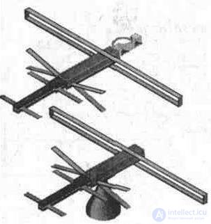
Fig. 3. 12. The appearance of the antenna "DEXTA"
Technical parameters "DEXTA"
Reception Channels ................................................ .. 1-5 ................. 6-12 ................ 21-68
Amplification, dB ............................................... ...... 8 ...................... 21 .................... 25
Reception angle ................................................ ....... 2x90 ° ............... 2x90 ° ................ 60 °
KZD, dB ................................................... .............. 0 ...................... 0 ............ ........... -sixteen
Technical parameters "DEXTA SUPERNOWA"
Reception Channels ................................................ .. 1 ... 5 ................. 6 ... 12 ................ 21 ... 68
Amplification, dB ........ 1 ...................................... ...... -30-8 .............. -10-23 ............. 0-32
Reception angle ................................................ ....... 2x90 ° ............... 2x90 ° ................ 60 °
KZD, dB ................................................... .............. 0 ...................... 0 ............ ........... -sixteen
The version of the antenna "Dexta Supernova" provides adjustment of the gain, which allows its use in areas with different levels of television signals.
Technical parameters of "DEXTA NOWA":
Reception Channels ................................................ .. 1 ... 5 ................. b ... 12 ................ 21 ... 68
Amplification, dB ............................................... ...... 8 ...................... 27 .................... 31
Reception angle ................................................ ....... 2x90 ° ............... 2x90 ° ................ 60 °
KZD, dB ................................................... .............. 0 ...................... 0 ............ ........... -sixteen
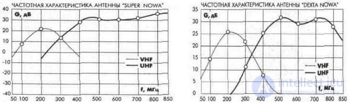
Reception of television channels of a meter range of waves is carried out on the loop vibrator (fig. 3. 15). matching device which is made on the transformer T1. In the decimeter wave band reception is carried out on the wave V - shaped vibrators. The matching with the addition filter is carried out by a transformer T2, made by the method of printed wiring. Through the addition filter (lowpass filter L3C1L4C3L5 and highpass filter C2W1C4W2C5) the television signal is fed to a two-stage amplifier. Correction of the frequency response in the first stage is carried out by the elements R1L6R4C7, and in the second - R5L7C9R6 and R8C11W3C10R7C8R3. Strip lines W1 ... W3 are also made by the method of printed wiring. Power amplifier (+ 12V) comes on the antenna cable with a separate power supply (ZS-X2). When using an antenna with a TV that has one common input jack, the signal is fed directly to the antenna input, using the ZS-X2 power supply. To work with TVs that do not have a common input, you need to connect a TV signal splitter to the antenna output. If you need to send a signal from one antenna to two TVs, you must use the power supply ZS-X3. Modernization of the antenna "DEXTA NOWA" by changing the design of the meter range vibrator allowed to obtain a stable reception on 1-5 channels. The antenna "DEXTA NOWA - R" also provides gain control, which allows it to be used in areas with different levels of television signals.
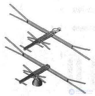
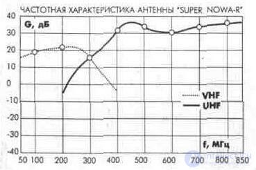
Fig. 3. 14. The appearance of the antenna "DEXTA SUPERNOWA-R".
Technical parameters "DEXTA SUPERNOWA-R":
Reception Channels ................................................ .. 1 -5 ................. 6-2 .................. 21 -68
Gain. dB ................................................. .... -30 ... 20 ............ -10 ... 22 ............. Oh ... 32
Reception angle ................................................ ....... 2x90 ° ............... 2x90 ° ................ 60 °
KZD, dB ................................................... .............. 0 ...................... 0 ............ ........... -sixteen

Fig. 3.15. Schematic diagram of the antenna DEXTA NOWA
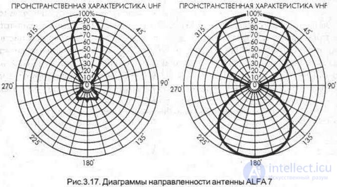
3. 2. 5. Active broadband antenna "ALFA 7"
Further improvement of the design of the DEXTA antennas was embodied in the design of the ALFA 7 antenna (Fig. 3. 16). The introduction of the reflector allowed to significantly increase the directional coefficient of the antenna. Adjusting the gain in this antenna allows you to use it in areas with different levels of television signals and areas of uncertain reception.

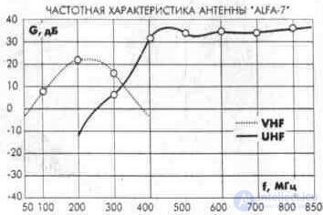
Fig. 3. 16. Antenna ALFA 7
Technical parameters of ALFA 7
Reception Channels ................................................ .. 1-5 ................. 6-12 ................ 21 -69
Amplification, dB ............................................... ...... -30 ... 8 .............. -10 ... 23 ............. 0 ... 35
Reception angle ................................................ ....... 2x90 ° ............... 2x90 ° ................ 60 °
KZD. dB ................................................. ............ 0 ...................... 0 .............. ......... -sixteen
3. 2. 6. Active broadband antenna "Gamma PLUS"
Broadband active antennas "Gamma PLUS" (Fig. 3. 18) have a built-in low-noise amplifier of television signals connected directly to active vibrators. Designed to work in conditions of different signal levels and installation both indoors and out. For this purpose, the antenna kit has a stand and a mast mount.
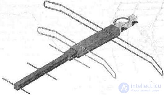
Fig. 3. 18. Gamma PLUS antenna.
Technical parameters of the Gamma Plus antenna:
Reception Channels ................................................ .. 1-5 ................. 6-12 ................ 21 -60
Amplification, dB ............................................... ...... 5 ...................... 24 ... 26 ............ 33 ... 35
Reception angle ................................................ ....... 2x90 ° ............ 2x90 ° .............. 60 °
KZD. dB ................................................. ............ 0 ...................... 0 .............. ......... -sixteen
Reception meter and decimeter waves is carried out on loop vibrators (Fig. & 3. 19). Согласование вибраторов с фильтрами сложения осуществляется трансформаторами Т1 и Т2. Через устройство сложения сигналов (ФНЧ L1C1L2 и ФВЧ C2L3C3) телевизионный сигнал через емкость С4 подается на двухкаскадный усилитель, выполненный на малошумящих транзисторах VT1, VT2. АЧХ усилителя корректируют элементы R4R5C9 и C10R6. Питание на усилитель (+ 12V) поступает по антенному кабелю с отдельного блока питания.
Технические параметры антенны Gamma Plus 2L Каналы приема.................................................. 1... 5................. 6... 12................ 21... 60
Усиление, дБ..................................................... 12-16............... 20-22................ 33-35
Угол приема....................................................... 2х90°............. 2х90°.............. 60°
КЗД, дБ............................................................. 0...................... 0....................... -16
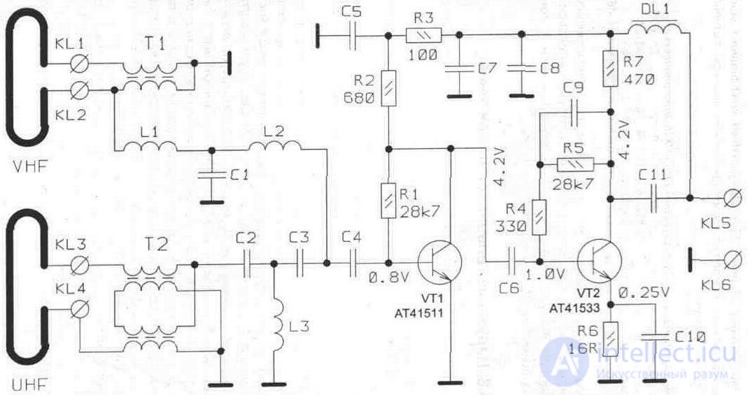
Fig. 3. 19. Принципиальная схема антенны «Gamma PLUS».
В версии антенны «Gamma Plus 2L» увеличен коэффициент усиле- ния на 1-5 телевизионных каналах за счет увеличения размерна петлевого вибратора MB диапазона. Технические параметры антенны Gamma Plus LUX (телескопическая):
Каналы приема.................................................. 1 -5................. 6-12................ 21 -60
Усиление, дБ..................................................... 12... 16............. 24... 26.............. 33... 35
Угол приема, град............................................. 2х90°............. 2х90.............. 60°
KZD, dB ................................................... .............. the ability to change the angle of reception -16 In the version of the antenna "Gamma Plus Lux" used telescopic tunable dipole MB range, which allows you to adjust to the received channel in the meter wavelength range, as well as change reception angle (radiation pattern).

Comments
To leave a comment
Television and antennas. Theory. Broadcast and cable. Digital and analog
Terms: Television and antennas. Theory. Broadcast and cable. Digital and analog