Lecture
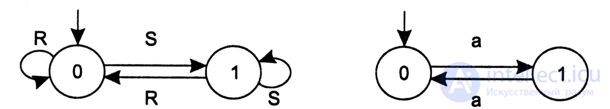
The trigger is the simplest automaton. Consider the two most common types of triggers: RS trigger and count trigger. The states of these automata are their output, i.e. these are Moore's machines. In the RS-trigger two inputs: Reset and Set . Reset input resets, a Set establishes a single state machine (Fig. 5.12a).
a) b)
Fig. 5.12
In a counting trigger (Fig. 5.12b), a single counting input switches the automaton from the zero state to the single state and back. A similarly similar trigger was described in detail in section 5.2.
Electronic clocks are one of the most widely used electronic devices in everyday life, the control of which is based on the state machine model. The simplest digital watches usually show the time, date and give the opportunity to set the time and date. These capabilities are controlled by a built-in automaton transducer, whose inputs are the events of pressing external control buttons. The block diagram of the electronic clock is shown in Fig. 5.13

Fig.5.13
Have 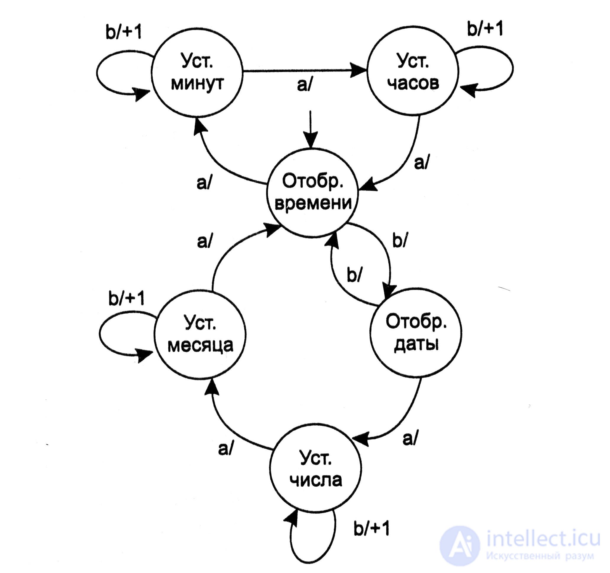 The ruling buttons on the clock are labeled "a" and "b". In addition to the display device, which highlights the numbers, as well as the display scheme that converts binary-decimal codes of numbers to the seven-digit LED control code, the map shows four display registers. These registers store the four-digit BCD codes that are currently displayed on the dial using the circuit and display device. Also shown are combinational schemes "OR", passing any of the allowed codes to the display registers and the "Management" bus, allowing in each situation the issuance to the signal display registers of either a stopwatch, or a clock, or a date. The circuit also contains stopwatch registers and a generator of ticks, which outputs a signal with a frequency of 1 Hz.
In sequential automata, the same set of states of input symbols can determine different states of output functions at different clock moments of the cycle. For example, at one of the stages of the cycle τ v with a set of inputs x 1 = 1, x 2 = 0, x 3 = 0, the output function y 1 = 0, and at some other stage of the cycle τ v + i with the same set of inputs, the output function y 1 = 1.Pig. 5.14
The control unit that organizes the work of all elements of the electronic clock is based on the model of the finite state machine. The transition graph of this automaton is shown in Fig. 5.14. In the initial state, the time is displayed. This means that the binary code of this state (after decryption) opens the outputs of four binary-decimal registers that store units and tens of minutes and units and tens of hours to the inputs of four combinational circuits "OR".
The state machine responds to the event of pressing the button “a” on the case of the clock by switching to the state “Setting minutes”, in which the event of pressing the button “b” will cause an increase in the number stored in the registers set aside for minutes. In this case, transfers from the register of seconds to the register reserved for storing numbers are blocked. The event of pressing the “b” button in the “Month Setting” will cause an increase in the number stored in the registers reserved for the month.
Reactive systems. A special class of systems should be distinguished, which are called “reactive” or “reactive” systems (reactive systems). These are systems interacting with the environment and reacting to the flow of external events. They consist of several subsystems, and the interaction of subsystems is part of the interaction of the system with its environment. A micro calculator, an electronic clock, a subway control system - all these are jet systems. The model of a finite automaton is a convenient means of describing such systems: it has semantic clarity, clarity and expressiveness and at the same time is rather strict and formal. However, the classic graphic representation of finite automata suffers from a number of drawbacks. The main disadvantage is the lack of a concept of time. Other disadvantages are the lack of a hierarchy of states, a generalization of transitions, means of expressing interruptions and continuing normal work after they are processed.
A simple extension of the classical finite automaton model is the introduction of the concept of an “external event”, the occurrence of which can be considered the condition for the automaton transition from state to state. Such events can be a receipt of a symbol or a whole message, an interrupt, a timer triggering event at the input of the automaton. The concept of time in the automaton is naturally associated with this last type of event. Indeed, the introduction of the concept of time is easiest to associate with the limitation of the time the automaton stays in a particular state, and such a limitation is set by the timer. A timer event will cause the machine to transition to another state.
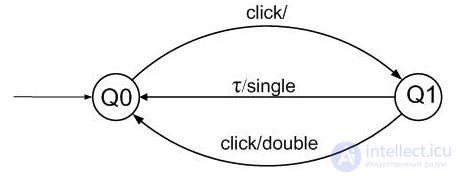
Pic.5.15
Consider as an example the task of specifying a process that defines single or double click. A double click is considered a pair of mouse clicks, shared by less than τ = 250 ms. In fig. Figure 5.15 shows the transition graph of the automaton solving this problem. At the first mouse click ( click ), the automaton enters the Q1 state, and if before the expiration of τ = 250 ms, another click signal event arrives at the automaton input, then a double signal will be output , otherwise the single signal .
In many applications, the conventional state machine model is extended by adding variables. For one of the variables with a finite scope, the special name state can be used . Possible states of such an automaton are characterized by sets of values of all variables of the corresponding program. In this way, a correspondence is achieved between a software representation of the behavior of the reactive system and a graphical representation of states and transitions.
Another widely used extension of the classical state machine model are statecharts introduced by D. Harel. The peculiarity of such a “state map” is the presence of a hyper-state that combines several states that have an identical reaction to the same event. Management when returning to the hyper state is transferred to the state in which the system was last time before it left the hyper state. Transitions between states in such a model are caused either by conditions (the onset of the truth of the predicate over the internal variables of the automaton, for example, the condition of exhaustion of the buffer) or by events. Events in state diagrams are external automaton events. This is usually the reception of control or informational messages from the environment.
Consider the use of Statecharts as an example . the simplest machine that regulates the pedestrian crossing . External events of the machine are the events of pushing the request-button on the sidewalk by pedestrians and the exhaustion of the time-out. It is natural to build an automaton as Moore’s automaton, in which the output — the regulation of the traffic light and the enabling signal for the transition — are potential signals that are state functions (Fig. 5.16).

Fig. 5.16
The output of the automatic machine in each state is represented by a pair: < Traffic light of transport; pedestrian traffic lights >. For example, in the state of Q1, the controlling automaton sets < 3 ; K >, i.e. green lights for vehicles and red for pedestrians; in the state of Q6 is set < Ж, К ; K >, i.e. yellow and red light transport (prepare) and red - pedestrians. In the initial state Q0, transport is allowed, and pedestrians are prohibited. In states Q4, Q5, when a traffic signal is prohibited, a green signal flashes to pedestrians every t0 seconds for t2 seconds. The transition request is accepted only in the Q0 state; in other states it is ignored. Delays (timeouts t0 - t3) are set at the moment when the automaton transitions to this state, after the timeout has expired, the automaton changes to the next state. In the hyper-state G, which unites a pair of states Q4 and Q5, the automaton is exactly t2 seconds: internal transitions do not break the timeout. For this, it is convenient to use the hyper-state of G.
A finite state machine as an information converter is a powerful model, however, there are algorithmic problems that cannot be solved with the help of a finite state machine. One of these problems is the problem of multiplying binary numbers .
Theorem 5.2. Multiplication of binary numbers cannot be performed using a finite state machine.
The proofs of the theorem are by contradiction.
Suppose that such a state machine exists. Let it have n states. Let us feed two identical binary numbers 2n + 1 to the input of the automaton. Each of these input numbers is written n + 2 binary digits. The automaton performing the multiplication receives n + 1 pairs of zeros as input, followed by a pair of ones — a sequential representation of the pair of input arguments. The automaton, if it exists, should produce the number 22n + 2 as a result, i.e. it must return 2n + 2 zeros, followed by a one. In other words, after the automaton receives n + 2 input signals, it, going offline, should give n more zeros, for which it should give one (see. Fig. 5.17).
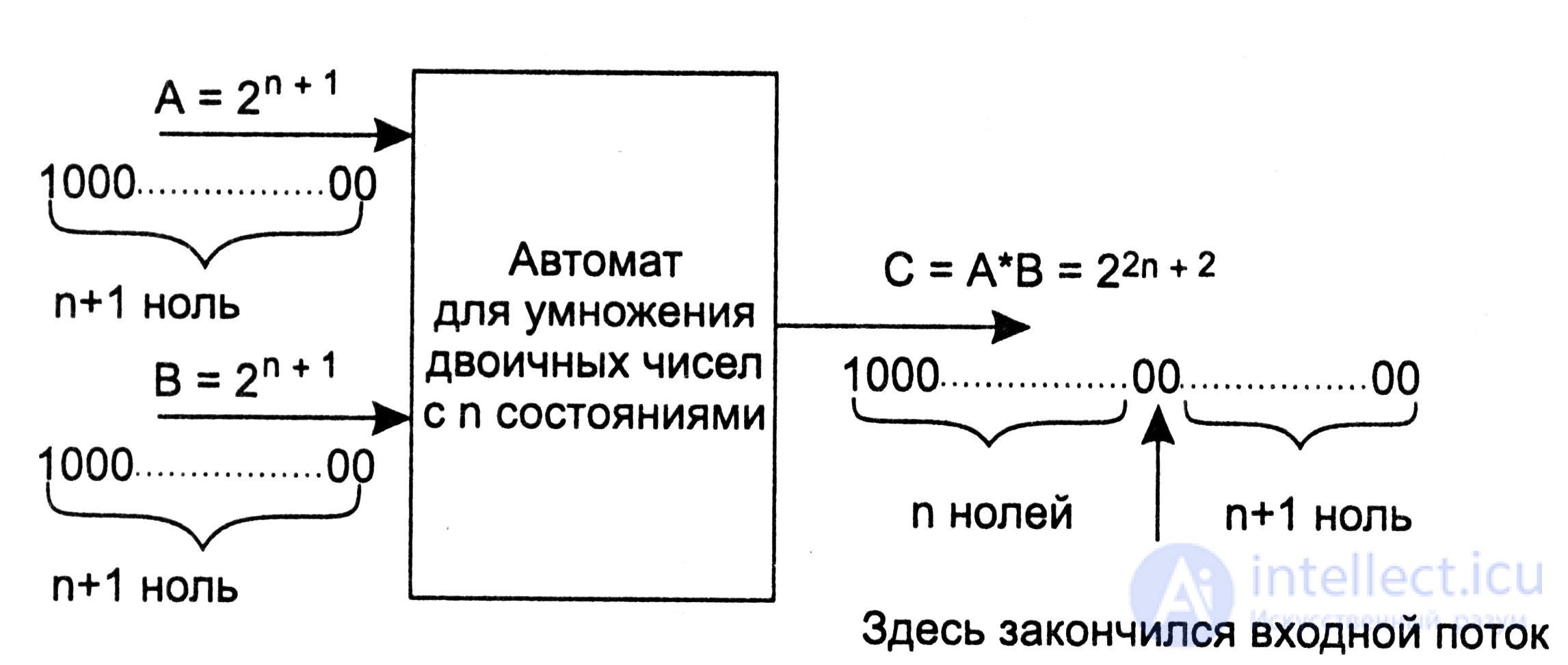
Fig. 5.17
However, it is obvious that no finite state machine with n states, operating in autonomous mode (i.e. under the action of only synchronization input signals), can output n zeros to the output, followed by one, since the maximum cycle in an automaton with n states does not exceed n.
The impossibility of constructing a finite automaton for solving this problem is a reflection of the fact that the amount of information that such an automaton should have “remembered” increases without bound as the values of the initial numbers increase. At the same time, to perform the task of adding any two binary numbers, the automaton needs only two states, one of which remembers the presence, and the other the lack of transfer to the next digit.

Comments
To leave a comment
Finite state machine theory
Terms: Finite state machine theory