Lecture
Even at the beginning of the twentieth century there was a very fundamental debate between the luminaries of electrical engineering. Which current is more profitable to transmit to the consumer over long distances: direct or alternating? Supporters of the transmission of alternating current via high-voltage lines from the substation to the consumer won the scientific dispute. This system is adopted worldwide and is still in operation successfully.
But most electronic equipment, and not only household, but also industrial, is powered by constant voltages and this has led to the creation of a whole branch of electrical engineering - the conversion (rectification) of alternating current. After the electron lamp was forgotten, the semiconductor diode became the main element of any rectifier .
The circuitry of rectifiers is very extensive, but the simplest is a half-wave rectifier .
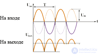
The voltage from the secondary winding of the power transformer is supplied to one single diode. Here is a diagram.
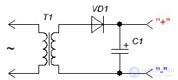
Therefore, the rectifier is also called half-wave. Only one half-cycle is rectified and a pulse voltage is obtained at the output. Its shape is shown in the figure.
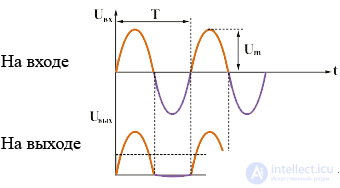
The scheme is simple and does not require a large number of elements. This affects the quality of the rectified voltage. At low frequencies of alternating voltage (for example, as in the power supply network - 50 Hz), the rectified voltage turns out to be very pulsating. And this is very bad.
In order to reduce the ripple voltage of the rectified voltage, it is necessary to take the value of the capacitor C1 very large, of the order of 2000-5000 microfarads, which increases the size of the power supply, since the electrolytes by 2000-5000 microfarads are quite large. Therefore, at low frequencies, this circuit is practically not used. But half-wave rectifiers have proven themselves in switching power supplies operating at frequencies of 10-15 kHz (kilohertz). At these frequencies, the filter capacity can be very small, and the simplicity of the circuit does not already affect the quality of the rectified voltage.
An example of using a half-wave rectifier is a simple charger from a cell phone. Since the charger itself is low-power, it uses a half-wave circuit, both in the input mains rectifier 220V (50Hz) and in the output where it is required to rectify the high-frequency alternating voltage from the secondary winding of the pulse transformer.
The undoubted advantages of such a rectifier include a minimum of parts, low cost and simple circuit solutions. In conventional (non-switching) power supplies for many decades, half-wave rectifiers have been operating successfully.
They come in two circuit designs: a mid-point rectifier and a bridge circuit known as the Gretz circuit. A mid-point rectifier requires a more complex power transformer, although there are half as many diodes as in a bridge circuit. The disadvantages of a half-wave rectifier with a midpoint can be attributed to the fact that in order to obtain the same voltage, the number of turns in the secondary winding of the transformer should be two times more than when using a bridge circuit. And this is not entirely economical in terms of spending copper wire.
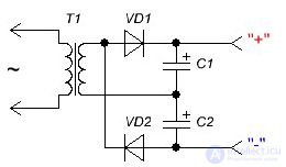
The figure below shows a typical half-wave rectifier with a midpoint .
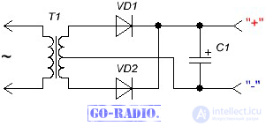
The magnitude of the ripple of the rectified voltage is less than that of a half-wave rectifier, and the value of the filter capacitor can also be used much smaller. You can clearly see how the two-half-wave circuit works according to the figure.
As you can see, the output of the rectifier is already half the voltage "dips" - those ripples.
Actively used rectifier circuit with a midpoint in the output rectifiers of switching power supplies for PC . Since a lower number of turns of copper wire is required in the secondary winding of a high-frequency transformer, it is much more efficient to use this particular circuit. Diodes are used dual, i.e. those with a common housing and three terminals (two diodes inside). One of the conclusions is the general one (usually the cathode). In appearance, the dual diode is very similar to a transistor .

The most popular bridge circuit in household and industrial equipment . Take a look.
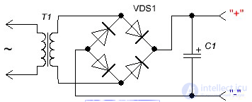
It is no exaggeration to say that this is the most common scheme. In practice, you will meet her more than once. It contains four semiconductor diodes, and the output, as a rule, is an RC filter or only an electrolytic capacitor to smooth out voltage ripples.
This circuit has already been described on the page about the diode bridge . It is worth noting that the bridge circuit also has drawbacks. As you know, any semiconductor diode has a so-called forward voltage drop ( Forward voltage drop - V F ). For ordinary rectifier diodes, it can be 1 - 1.2 V (depending on the type of diode). So, when using a bridge circuit on diodes, the voltage equal to 2 x V F is lost , i.e. about 2 volts. This is because 2 diodes are involved in the rectification of one half-wave of alternating current (then the other 2). It turns out that a part of the voltage that we remove from the secondary winding of the transformer is lost on the diode bridge, and this is obvious loss. thereforein some cases , Schottky diodes are used as part of the diode bridge, in which the direct voltage drop is small (about 0.5 volts). True, it is worth considering that the Schottky diode is not designed for large reverse voltage and is very sensitive to its excess.
Of great interest is the rectifier with a doubling voltage .
The principle of the Latur-Delon-Grenasher voltage doubler is based on the alternating charge-discharge of capacitors C1 and C2 with input polarity waves of different polarity. As a result, between the cathode of one diode and the anode of the second diode there is a voltage twice the input voltage. Scheme in the studio :)
It is worth noting that this circuit is not often used in power supplies. But it can be safely used if it is necessary to double the voltage that is removed from the secondary winding of the transformer. This will be a more logical and correct decision than rewinding the secondary winding of the transformer in order to increase the output voltage of the secondary winding by 2 times (because in this case you will have to wind the secondary winding with twice as many turns). So, if you could not find a suitable transformer - feel free to use this circuit.
The development of the circuit was the creation of a multiplier on semiconductor diodes.
Each diode and capacitor form a "link" and these links can be connected in series until a voltage of several tens of kilovolts is obtained. Of course, for this, the input voltage must also be large enough.
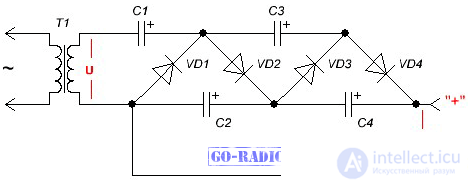
The figure shows a four-link multiplier and at the output we get a voltage four times the input voltage ( U ). These rectifiers are widely used where you need to get a high voltage at a fairly low current. For example, according to this scheme, high voltage sources were made in old televisions and oscilloscopes to power the anode of a cathode ray tube.
Now such power sources are used in scientific laboratories, in particle detectors, in medical equipment (Chizhevsky chandelier) and in self-defense weapons (stun gun). When repeating such designs and selecting parts, you should take into account the operating voltage of both diodes and capacitors based on the voltage that you want to receive. The entire multiplier, as a rule, is filled with a special compound or epoxy resin in order to avoid high-voltage breakdowns between circuit elements.
For the normal operation of some devices, such as the Chizhevsky chandelier, sufficiently high voltages are required. According to experts, the emitter of negative air ions is effective only at a voltage of at least 60 kilovolts.
Devices that are used to obtain direct current from an alternating three-phase current are called three-phase rectifiers. Three-phase rectifiers in household appliances, of course, are not used. The only device that can be used in everyday life is a welding machine. As three-phase rectifiers are used the developments of two well-known electrical engineers Mitkevich and Larionov. Mitkevich’s simplest circuit is called “three quarters of the bridge in parallel”, which means three power diodes connected in parallel through the secondary windings of a three-phase transformer. Scheme.
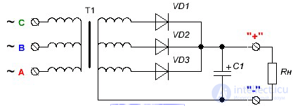
The ripple factor at the load is very small, which allows the use of filter capacitors of small capacity and small dimensions.
More complex is the Larionov scheme, which is called "three half-bridges in parallel," which is clearly seen from the figure.
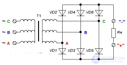
The circuit uses six diodes and a slightly different switching circuit. In general, there are a lot of circuits of three-phase rectifiers and the most perfect, although rarely used is the "six bridges in parallel" circuit, and this is 24 diodes! But this circuit can produce high voltage at high power.
Three-phase powerful rectifiers are used in electric locomotives, urban electric vehicles (trams, trolleybuses, subways), and in industrial plants for electrolysis. Also, industrial systems for cleaning gas mixtures, drilling and welding equipment use three-phase rectifiers.
Now you know what AC rectifiers are and you can easily find them on the circuit diagram or on the printed circuit board of any device. And for those who want to know more, we recommend that you read the book "Semiconductor Rectifiers" .

Comments
To leave a comment
Power supplies for electronic equipment
Terms: Power supplies for electronic equipment