A computer power supply unit (English power supply unit, PSU - power supply unit, PSU ) is a secondary power source designed to supply computer components with direct current electric power by converting the mains voltage to the required values.
To some extent, the power supply also:
- performs the functions of stabilization and protection from minor interference power supply;
- participates in cooling components of a personal computer.
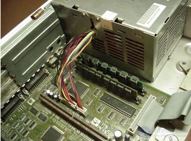
Connected PSU in IBM PS / 2
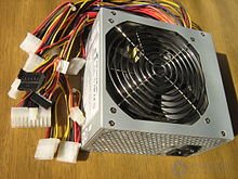
450 W Switching Power Supply for Personal Computer
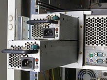
Duplicating a hot-swappable power supply in a fault-tolerant server
A computer power supply for a PC standard PC, personal or gaming, according to the ATX2.x specification, must provide output voltages of ± 5, ± 12, +3.3 Volts, and also +5 Volt standby mode.
- The main power circuits are voltages +3.3, +5 and +12 V. Moreover, the higher the voltage, the more power is transmitted through these circuits. Negative supply voltages (−5 and −12 V) allow small currents and are practically not used in modern motherboards at the present time.
- A voltage of −5 V was used only by the ISA interface of the motherboards. To provide −5 VDC in ATX and ATX12V versions up to 1.2, pin 20 and a white wire were used. This voltage (as well as contact and wire) is not mandatory already in version 1.2 and is completely absent in versions 1.3 and later.
- A voltage of −12 V is only necessary for the full implementation of the RS-232 serial interface standard using chips without an integrated inverter and voltage multiplier, and therefore is also often not available.
- Voltages of ± 5, ± 12, +3.3 V standby mode are used by the motherboard. For hard drives, optical drives, fans, only voltages of +5 and +12 V are used.
- Modern electronic components use a supply voltage not higher than +5 Volt. The most powerful consumers of energy, such as a video card, a central processor, a north bridge, are connected via secondary converters with power supply from both +5 V and +12 V circuits placed on the motherboard or on a video card.
- Voltage +12 V is used to power the most powerful consumers. Separation of the supply voltages on 12 and 5 V is advisable both to reduce the currents along the printed conductors of the boards, and to reduce the energy losses in the output rectifier diodes of the power supply.
- The voltage of +3.3 V in the power supply unit is formed from the voltage of +5 V, and therefore there is a limit on the total power consumption of ± 5 and +3.3 V.
In most cases, a pulsed power supply unit is used, made according to a half-bridge (push-pull) scheme. Power supplies with energy-saving transformers (flyback circuit) are naturally limited in power by the dimensions of the transformer and therefore are used much less frequently.
Device (circuitry)
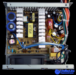
Computer switching power unit (ATX) with the cover removed: A - input
diode rectifier , below you can see the
input filter ; B - input
smoothing capacitors , to the right is the radiator of
high-voltage transistors ; C -
pulse transformer ; to the right is the radiator of low-voltage
diode rectifiers ; D -
group stabilization choke ; E -
output filter capacitors
A widespread switching power supply circuit consists of the following parts:
Input circuits
- Input filter that prevents the propagation of impulse noise in the power network [1] . Also, the input filter reduces the inrush of the charge current of electrolytic capacitors when the power supply unit is turned on (this can cause damage to the input rectifier bridge).
- In high-quality models, a passive (cheap) or active power corrector (PFC) reduces the load on the supply network.
- Input rectifier bridge that converts alternating voltage into a constant pulsating.
- Condenser filter, smoothing ripples of rectified voltage.
- A separate low-power power supply, issuing +5 V standby mode mat. boards and +12 V for powering the converter IC of the UPS itself. Usually it is designed as a flyback converter on discrete elements (either with group stabilization of output voltages through an optocoupler plus an adjustable TL431 zener diode in the operating circuit, or 7805/7812 linear regulators at the output) or (in top models) on a TOPSwitch type chip.
Converter
- Half-bridge converter on two bipolar transistors
- The control circuit of the converter and the protection of the computer from over / undervoltage, usually on a specialized chip (TL494, UC3844, KA5800, SG6105, etc.).
- Pulsed high-frequency transformer, which is used to form the required voltage ratings, as well as for galvanic isolation of circuits (input from the output, as well as, if necessary, output from each other). The peak voltage at the output of the high-frequency transformer is proportional to the input supply voltage and significantly exceeds the required output.
- Feedback circuits that maintain a stable voltage at the output of the power supply.
- PG voltage driver (Power Good, “voltage is normal”), usually on a separate OU.
Output circuits
- Output rectifiers. Positive and negative voltages (5 and 12 V) use the same output windings of the transformer, with different direction of rectifier diodes switching. To reduce losses, with a high current consumption, Schottky diodes with a small direct voltage drop are used as rectifiers.
- Throttle output group stabilization. The choke smoothes the pulses, accumulating energy between pulses from the output rectifiers. Its second function is the redistribution of energy between the output voltage circuits. So, if the current consumed by any channel increases, which lowers the voltage in this circuit, the group stabilization choke as a transformer will proportionally lower the voltage on other output circuits. The feedback circuit will detect a drop in output voltage and increase the total energy supply, which will restore the required voltage values.
- Output filter capacitors. The output capacitors, together with the group stabilization choke, integrate the pulses, thereby obtaining the necessary voltages, which, thanks to the group stabilization choke, are significantly lower than the voltages from the output of the transformer.
- One (on one line) or several (on several lines, usually +5 and +3.3) load resistors 10-25 Ohm, to ensure safe operation at idle.
The advantages of such a power supply:
- Simple and time-tested circuit technology with a satisfactory quality of output voltage stabilization.
- High efficiency (65-70%). The main losses occur in transients, which last much less time than a steady state.
- Small dimensions and weight, due to both low heat generation on the regulating element and small dimensions of the transformer, due to the fact that the latter operates at high frequency.
- Low metal consumption, so that powerful switching power supplies are cheaper than transformer, despite the greater complexity.
- The ability to connect to networks with a wide range of voltages and frequencies, or even DC networks. Due to this, it is possible to unify the equipment produced for various countries of the world, and hence its cheapening during mass production.
The disadvantages of the half-bridge power supply unit on bipolar transistors:
- When constructing power electronics circuits, the use of bipolar transistors as key elements reduces the overall efficiency of the device [2] . Control of bipolar transistors requires a significant amount of energy.
More and more computer power supplies are built on more expensive powerful MOSFET transistors. The circuit design of such computer power supplies is implemented both in the form of half-bridge circuits and flyback converters. To meet the weight and size requirements for a computer power supply unit, much higher conversion frequencies (100-150 kHz) are used in the flyback converters.
- A large number of winding products, individually designed for each type of power supply. Such products reduce the manufacturability of BP.
- In many cases, insufficient stabilization of the output voltage through the channels. The group stabilization choke does not allow to provide voltage values in all channels with high accuracy. More expensive, as well as powerful modern power supplies, generate voltages of ± 5 and 3.3 V using secondary transducers from channel 12 V.
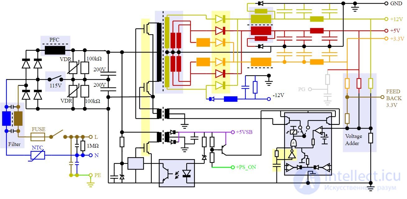
Schematic diagram of the power supply unit of a personal computer
Standards
AT (outdated)
See also: AT (form factor)
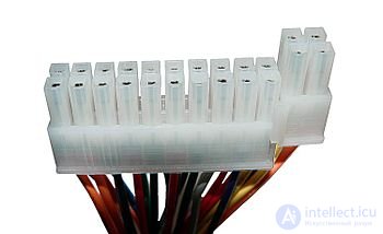
One of two six-pin AT power connectors
In the power supply units of AT form factor computers, the power switch breaks the power circuit and is usually placed on the front panel of the case with separate wires; Power supply with corresponding circuits is absent in principle. However, almost all AT + ATX standard motherboards had a power supply control output, and power supplies, at the same time, an input that allows an AT standard motherboard to control it (turn it on and off).
The AT power supply connects to the motherboard with two six-pin connectors that plug into one 12-pin connector on the motherboard. Multi-colored wires go to the connectors from the power supply, and the connection is correct when the contacts of the connectors with the black wires converge in the center of the motherboard connector. The pinout of the AT connector on the motherboard is as follows:
| one |
2 |
3 |
four |
five |
6 |
7 |
eight |
9 |
ten |
eleven |
12 |
| |
- |
|
|
|
|
|
|
|
|
|
|
| PG |
empty |
+ 12V |
-12V |
common |
common |
common |
common |
-5V |
+ 5V |
+ 5V |
+ 5V |
ATX (modern)
See also: ATX
20-pin ATX connector (view of the motherboard)
At the 24-pin ATX connector, the last 4 pins can be removable to ensure compatibility with the 20-pin socket on the motherboard
| Output |
Tolerance |
Minimum |
Nominal |
Maximum |
unit of measurement |
| + 12V1DC [3] |
± 5% |
+11.40 |
+12.00 |
+12.60 |
Volt |
| + 12V2DC [4] |
± 5% |
+11.40 |
+12.00 |
+12.60 |
Volt |
| +5 VDC |
± 5% |
+4.75 |
+5.00 |
+5.25 |
Volt |
| +3.3 VDC [5] |
± 5% |
+3.14 |
+3.30 |
+3.47 |
Volt |
| −12 VDC |
± 10% |
−13.20 |
−12.00 |
−10,80 |
Volt |
| +5 VSB |
± 5% |
+4.75 |
+5.00 |
+5.25 |
Volt |
- ↑ to comply with the requirements of the legislation of countries on electromagnetic radiation, in Russia - the requirements of SanPiN 2.2.4.1191-03 2.2.4.1191-03.htm “Electromagnetic fields in a production environment, in the workplace. Sanitary-epidemiological rules and regulations "
- ↑ B.Yu. Semenov Power electronics: from simple to complex. - M .: SOLOMON-Press, 2005. - 415 p. - (Engineer's library).
- ↑ At a peak load of +12 VDC, the output voltage range of +12 VDC can fluctuate within ± 10.
- ↑ Minimum voltage level of 11.0 VDC during the peak load of +12 V2DC.
- ↑ Shutter speed range required by mainboard power connector and S-ATA power connector.
Increased requirements for +5 VDC - now the PSU must deliver a current of at least 12 A (+3.3 VDC - 16.7 A, respectively, but the total power should not exceed 61 W) for a typical power consumption system of 160 W. The output power was skewed: before, the main channel was +5 V, now the requirements for minimum current +12 V were dictated. The requirements were due to a further increase in the power of components (mainly video cards), whose requirements could not be met by +5 V lines for very high currents in this line.
Typical system, power consumption 160 W
| Output |
Minimum |
Nominal |
Maximum |
Unit
measuring |
| + 12VDC |
1.0 |
9.0 |
11.0 |
Ampere |
| +5 VDC |
0.3 |
12.0 [1] |
+5.25 |
Ampere |
| +3.3 VDC |
0.5 |
16.7 [1] |
|
Ampere |
| −12 VDC |
0.0 |
0.3 |
|
Ampere |
| +5 VSB |
0.0 |
1.5 |
2.0 |
Ampere |
Typical system, power consumption 180 W
| Output |
Minimum |
Nominal |
Maximum |
Unit
measuring |
| + 12VDC |
1.0 |
13.0 |
15.0 |
Ampere |
| +5 VDC |
0.3 |
10.0 [2] |
+5.25 |
Ampere |
| +3.3 VDC |
0.5 |
16.7 [2] |
|
Ampere |
| −12 VDC |
0.0 |
0.3 |
|
Ampere |
| +5 VSB |
0.0 |
1.5 |
2.0 |
Ampere |
Typical system, power consumption 220 W
| Output |
Minimum |
Nominal |
Maximum |
Unit
measuring |
| + 12VDC |
1.0 |
15.0 |
17.0 |
Ampere |
| +5 VDC |
0.3 |
12.0 [3] |
|
Ampere |
| +3.3 VDC |
0.5 |
12.0 [3] |
|
Ampere |
| −12 VDC |
0.0 |
0.3 |
|
Ampere |
| +5 VSB |
0.0 |
2.0 |
2.5 |
Ampere |
Typical system, power consumption 300 W
| Output |
Minimum |
Nominal |
Maximum |
Unit
measuring |
| + 12VDC |
1.0 |
18.0 |
18.0 |
Ampere |
| +5 VDC |
1.0 |
16.0 [4] |
nineteen |
Ampere |
| +3.3 VDC |
0.5 |
12.0 [4] |
|
Ampere |
| −12 VDC |
0.0 |
0.4 |
|
Ampere |
| +5 VSB |
0.0 |
2.0 |
2.5 |
Ampere |
- ↑ Go to: 1 2 The aggregate power of +3.3 VDC and +5 VDC lines should not exceed 61 W
- ↑ Go to: 1 2 The aggregate power of +3.3 VDC and +5 VDC lines should not exceed 63 W
- ↑ Go to: 1 2 The aggregate power of +3.3 VDC and +5 VDC lines should not exceed 80 W
- ↑ Go to: 1 2 The aggregate power of +3.3 VDC and +5 VDC should not exceed 125 W
Power / Power Connector
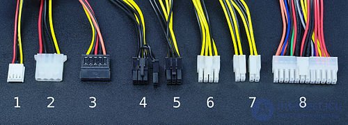
Plugs loops power (from the power supply), without adapters and adapters
1)
AMP 171822-4 mini size for powering 5 and 12 volts of a peripheral device (usually a disk drive)
2) Molex regular size (
molex 8981 )
3)
MOLEX 88751 5-pin connectors for powering the device with the
MOLEX 675820000 interface:
MOLEX 675820000 or equivalent with
Molex 675810000 or equivalent
[1]
4) “PCIe8connector” for video card power split into “PCIe6connector” (for video card power)
5) "PCIe6connector" to power the video card
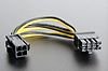
6) "EPS12V" (English
Entry-Level Power Supply Specification for powering the motherboard
7) "ATX PS 12V" ("P4 power connector") to power the motherboard
8) "ATX12V" main power supply of the motherboard:
MOLEX 39-01-2040 или эквивалентная with
Molex 44476-1112 (HCS) contacts
Molex 44476-1112 (HCS) or equivalent
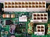
- The 20-pin main power connector + 12V1DCV was used with the first ATX form factor motherboards, before the advent of PCI-Express motherboards.
- 24-pin connector of the main power supply + 12V1DC (plug type
MOLEХ 24 Pin Molex Mini-Fit Jr. PN# 39-01-2240 или эквивалентная on the side of the PSU with contacts of the type Molex 44476-1112 (HCS) или эквивалентная ; socket of the counterpart on the mother Molex 44206-0007 or equivalent) is designed to support motherboards with a PCI Express bus that consumes 75 watts [2] . Most motherboards running on the ATX12V 2.0 also support ATX v1.x power supplies (4 pins remain unused), for this some manufacturers make the new four pins detachable.
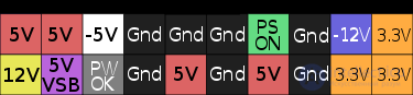
24-pin power connector motherboard ATX12V 2.x
(The 20-pin has no last four: 11, 12, 23 and 24)
| Colour |
Signal |
Contact |
Contact |
Signal |
Colour |
| Orange |
+3.3 V |
one |
13 |
+3.3 V |
Orange |
| +3.3 V sense |
Brown |
| Orange |
+3.3 V |
2 |
14 |
−12 V |
Blue |
| The black |
Land |
3 |
15 |
Land |
The black |
| Red |
+5 v |
four |
sixteen |
Power on |
Green |
| The black |
Land |
five |
17 |
Land |
The black |
| Red |
+5 v |
6 |
18 |
Land |
The black |
| The black |
Land |
7 |
nineteen |
Land |
The black |
| Gray |
Power good |
eight |
20 |
−5 V |
White |
| Violet |
+5 VSB [3] |
9 |
21 |
+5 v |
Red |
| Yellow |
+12 V |
ten |
22 |
+5 v |
Red |
| Yellow |
+12 V |
eleven |
23 |
+5 v |
Red |
| Orange |
+3.3 V |
12 |
24 |
Land |
The black |
- The three shaded contacts (8, 13, and 16) are control signals, not power.
- “Power On” is pulled up to a resistor of up to +5 Volts inside the power supply, and must be low to turn on the power.
- “Power good” is kept at a low level, while the other outputs have not yet formed the voltage of the required level.
- The “+3.3 V sense” wire is used for remote sensing [4] .
|
| Pin 20 (and white wire) is used to provide −5 VDC in ATX and ATX12V versions up to 1.2. This voltage is not mandatory already in version 1.2 and is completely absent in versions 1.3 and later. |
| In the 20-pin version, the right contacts are numbered from 11 to 20. |
| The orange +3.3 VDC wire and the brown 3.3.3 sense suspension, connected to pin 13, are 18 AWG thick; all others - 22 AWG |
- ATX PS 12V connectors and plugs (P4 power connector)
-
-
-
-
-
- PCIe6connector / PCIe8connector for additional power to high-powered video cards
-
-
Also located on the BP:
- The 4-pin “ ATX12V ” connector (also referred to as “ P4 power connector ”) is an auxiliary connector for powering the processor:
MOLEX 39-01-2040 или эквивалентная with Molex 44476-1112 (HCS) or equivalent; outlet mate on the motherboard type Molex 39-29-9042 or equivalent. 18 AWG wire.
In the case of building a high-consumption system (over 700 W), expands to " EPS12V " (English Entry-Level Power Supply Specification ) - an 8-pin auxiliary connector for powering the motherboard and 12 V processor,
- 4-pin connector for the drive with
AMP 171822-4 or equivalent. 20 AWG wire.
- 4-pin power connector for peripheral device such as a hard disk or optical drive with P-ATA interface: MOLEX
MOLEХ 8981-04P или эквивалентная type MOLEХ 8981-04P или эквивалентная with AMP 61314-1 or equivalent. 18 AWG wire.
- The 5-pin
MOLEX 88751 for powering SATA devices consist of an MOLEX 675820000 type MOLEX 675820000 or equivalent with Molex 675810000 or equivalent [1] .
- 6-pin or 8-pin power connectors for PCI Express x16 video cards.
At the end of the 2000s, a modular principle was applied for cable installation, when only the main 24 (20 + 4) -plug cable and 4 + 4-pin EPS12V power cable for the ATX12V / EPS12V motherboard, the other cable for peripherals are removable, on connectors. [5] .
Efficiency - 80 PLUS
The efficiency of a “conventional” power supply unit (described above) is around 65–70%. To obtain larger quantities, special circuit solutions are used.
80 PLUS certification (as part of the Energy Star 4.0 energy saving standard adopted in 2007) implies certification of computer power supplies for compliance with certain standards for energy efficiency: the power efficiency must be at least 80% at 20, 50 and 100% load relative to the rated power of the power supply, and the power factor should be 0.9 or higher at 100% load.
And although the 80 PLUS standard certification was originally carried out only for use in networks with a voltage of 115 V (which are common, for example, in the US, but not in Russia), and therefore the efficiency of 80 PLUS certified power supplies can be below 80% in 220/230 V networks, however, subsequent specification levels, starting from 80 PLUS Bronze, were certified for use in 230 V networks. However, 80 PLUS certified power supply units can have efficiency below 80% with loads less than 20%, which important enough as most PCs rarely work They melt at maximum power consumption, and more often idle. Also, the efficiency may be lower than that declared in the operating conditions of the PSU at a temperature other than room temperature (at which certification is carried out). [6]
In 2008, Bronze, Silver, Gold certification levels were added to the standard, Platinum in 2009, and Titanium in 2012:
| Percent of rated load |
ten% |
20% |
50% |
100% |
| 80 PLUS |
- |
80% |
80% |
80% |
| 80 PLUS Bronze |
- |
81% |
85% |
81% |
| 80 PLUS Silver |
- |
85% |
89% |
85% |
| 80 PLUS Gold |
- |
88% |
92% |
88% |
| 80 PLUS Platinum |
- |
90% |
94% |
91% |
| 80 PLUS Titanium |
90% |
94% |
96% |
91% |
Power required
The power delivered to the load by the existing power supply units largely depends on the power of the computer system and varies from 50 (embedded platforms of small form factors) to 1800 W (the most high-performance workstations, servers or gaming machines).
In the case of building a cluster, the calculation of the required amount of supplied energy takes into account the power consumed by the cluster, the power of the cooling and ventilation systems, the efficiency of which in turn is different from one. According to APC by Schneider Electric, for every watt power consumed by servers, 1.06 watts of cooling systems are required. The competent calculation is of particular importance when creating a data storage and processing center (DPC) by reserving by the formula N + 1 .
See also: TDP
Notebook Power Supplies
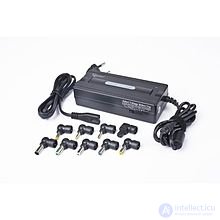
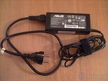
Universal charger for laptops.
Gembird NPA-AC1-GS, 90 W
The power supply for a laptop (and other mobile computers) is used both to charge its rechargeable battery (battery) and to work without a battery. By type of performance, a laptop's PSU is most often an external unit. Due to the fact that the electrical characteristics of different notebook models can vary greatly, there is not yet a single standard for external power supplies, and their power supplies are usually not interchangeable. There is an initiative to standardize notebook power supplies [7] .
- Laptop manufacturers often use different power connectors (there are several dozen of them known, although only a few are widely distributed, differing only in plug diameter [ source not specified 283 days ] ). Most of them are connected by coaxial cable with a positive internal conductor, although there are connectors with reverse polarity.
- The supply voltages differ: usually it is 18.5 V or 19 V, although there are variants with a voltage of 15 or 16 V (in the main subnotebooks); 19.5 V; 20 V or even 24 V (Apple).
- Power supplies have maximum output power, delivering a current of 3.16 A (for older types); 3.42 A; 4.74 A; 6.3 A; 7.9 A, depending on how powerful the computer is supposed to be powered.
The replacement of the notebook power supply should be approached with caution (the replacement should have the same polarity, the difference in the supply voltage not exceeding 0.5 V, and have sufficient power), otherwise it may lead to failure of the notebooks.
Also produced universal power supply, designed for laptops of different models and different manufacturers. Such a power supply unit has a voltage switch and a set of interchangeable plugs for connection.
 External images External images |
| Drawing BP FSP600-80GLN |
 |
Assembly drawing of PSU FSP600-80GLN in PDF format |
Power supplies for small computers
The appeared motherboards on the Intel NM10 Express Chipset with soldered Atom family processors (such as Intel BOXDN2800MT [8] ) do not have 24-pin connectors familiar to motherboards of personal computers; instead, the board is powered via a round connector with a direct current (English) Russian. from the outside. By varying a computer bundle built on the basis of such a motherboard, it is possible to vary the required power over a wide range. For example, if the assembled system will not have hard disks and optical drives (which require a voltage of 11 ... 12 volts), an eight-volt upper supply voltage threshold is sufficient to power on:
  • 8–19 V DC external external power supply
 power supply though DC jack on the back panel (Figure 13, A).  This connector
 accepts dual-barrel plugs with an inner diameter (ID) of 2.5 mm and an outer
 diameter (OD) of 5.5 mm, where the inner contact is +8 V DC (± 10%) through
 +19 V DC (± 10%) and the shell is Ground.  The maximum current rating for this
 connector is 8 A.
 • Internal Power Supply - the board can be
 internal 1 x 2 power connector (Figure 13, B), where pin 1 is Ground and pin 2 is
 +8 V DC (± 10%) through +19 V DC (± 10%).  The maximum current rating for
 this connector is 10 A.
- Intel Desktop Board DN2800MT. Product Guide (English)
Also, in table 39 “Typical System-Level Power Consumption Figures” of document [9] there is a calculation for selecting power parameters, depending on the system configuration elements involved.
Computer power supply manufacturers
- Antec
- Chieftec
- Cooler master
- Corsair
- LogicPower
- Exegate
- Foxconn
- FSP Group
- Gigabyte technology
- Thermaltake [10]
- OCZ
- Spirit
- SilverStone Technology
- Zalman
- Herolchi Electronic Co (hec)
- Prosource
- Delta electronics


Comments
To leave a comment
Power supplies for electronic equipment
Terms: Power supplies for electronic equipment